


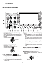
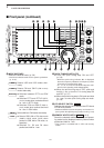
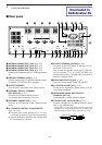
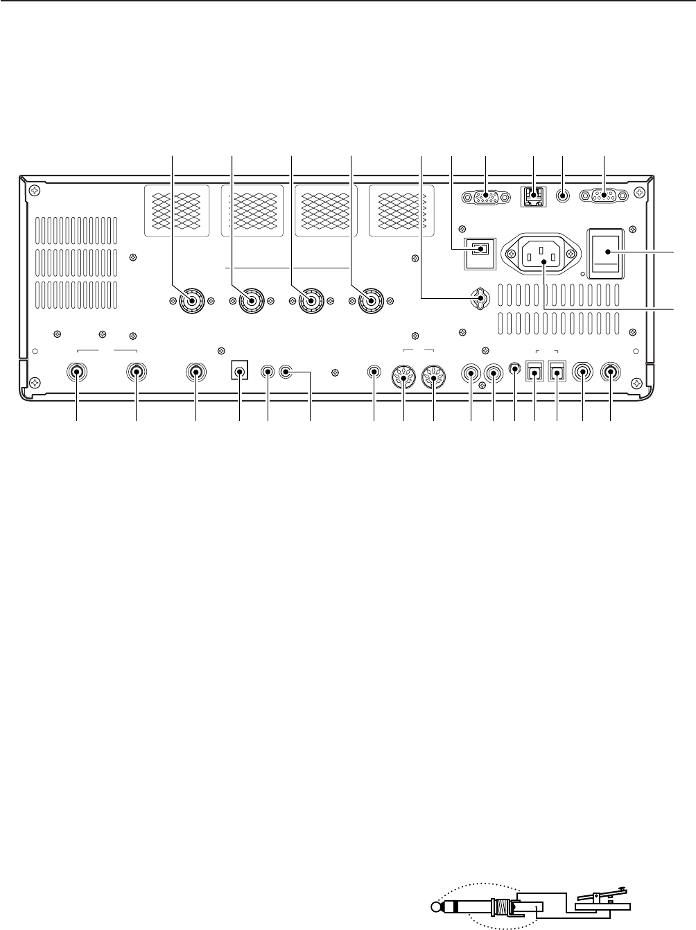
q ANTENNA CONNECTOR 1 [ANT 1] (p. 2-5)
w ANTENNA CONNECTOR 2 [ANT 2] (p. 2-5)
e ANTENNA CONNECTOR 3 [ANT 3] (p. 2-5)
r ANTENNA CONNECTOR 4 [ANT 4] (p. 2-5)
Accept a 50 Ω antenna with a PL-259 plug connec-
tor.
t GROUND TERMINAL [GND] (p. 2-4)
Connect this terminal to a ground to prevent electri-
cal shocks, TVI, BCI and other problems.
y CIRCUIT BREAKER
Cuts off the AC input when over-current occurs.
u EXTERNAL DISPLAY TERMINAL
[EXT-DISPLAY] (p. 2-7)
Connects to an external display monitor.
• At least 800×600 pixel display is necessary.
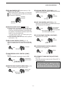
i ETHERNET CONNECTOR (p. 16-6)
Connects to a PC through a LAN (Local Area Net-
work).
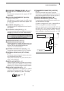
o CI-V REMOTE CONTROL JACK [REMOTE]
(pgs. 2-6, 14-2)
➥ Connects a PC via the optional CT-17
CI-V LEVEL
CONVERTER for external control of the transceiver.
➥ Used for transceive operation with another Icom
CI-V transceiver or receiver.
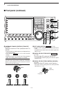
!0 RS-232C TERMINAL [RS-232C] (p. 2-6)
Connects an RS-232C cable, D-sub 9-pin to con-
nect the IC-7700 to a PC.
Can be used to remotely control the IC-7700 with-
out the optional CT-17, or for RTTY/PSK31 de-
coded signal output. The [RS-232C] interface is
wired as a modem (DCE).
!1 MAIN POWER SWITCH [I/O] (p. 3-2)
Turns the internal power supply ON and OFF.
!2 AC POWER SOCKET [AC] (p. 2-5)
Connects the supplied AC power cable to an AC
line-voltage receptacle.
!3 REFERENCE SIGNAL INPUT/OUTPUT
TERMINAL [REF I/O]
Inputs/outputs a 10 MHz reference signal.
!4 STRAIGHT KEY JACK [CW KEY] (p. 2-5)
Accepts a straight key or external electronic keyer
with
1
⁄
4
inch standard plug.
• [ELEC-KEY] on the front panel can be used for a
straight key or external electronic keyer. Deactivate the
internal electronic keyer in keyer set mode. (p. 4-12)
1-12
1
PANEL DESCRIPTION
ALC
ADJ
ALCRELAY
CW KEY
EXT
KEYPAD
METER
DC OUT
15V
MAX1A
REF I/O
10MHz
-
10dBm
INOUT
REMOTE
RS
-
232C
EXT
-
DISPLAY
RX ANT
INOUT
S/P DIF
12
ACC
EXT
-
SP
ANT 1
ANT 2
ANT 3
ANT 4
GND
AC
15A
I
X
-
VERTER
u i o !0
!4 !3!5!6!7!8!9@0@1@2@3@4@5@6@7@8
!1
!2
t yqwer
■ Rear panel
(+)
(_)