


1-13
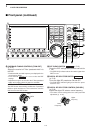
!5 S/P DIF INPUT TERMINAL [S/P DIF– IN] (p. 2-7)
!6 S/P DIF OUTPUT TERMINAL [S/P DIF– OUT]
(p. 2-7)
Connects external equipment that supports S/P DIF
input/output.
!7 ALC LEVEL ADJUSTMENT POT [ALC ADJ]
Adjusts the ALC levels.
No adjustment is required when the ALC output
level of a connected non-Icom linear amplifier is 0
to –4 V a DC.
!8 ALC INPUT JACK [ALC] (p. 2-8)
Connects to the ALC output jack of a non-Icom lin-
ear amplifier.
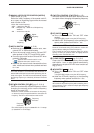
!9 T/R CONTROL JACK [RELAY] (p. 2-8)
Connects to ground when transmitting to control an
external unit, such as a non-Icom linear amplifier.
@0 ACCESSORY SOCKET 1 [ACC 1]
@1 ACCESSORY SOCKET 2 [ACC 2]
Enable connection of external equipment such as a
linear amplifier, an automatic antenna selector/
tuner, a TNC for data communications, etc.
• See p. 2-11 for socket information.
@2
EXTERNAL SPEAKER JACK [EXT-SP]
(p. 2-6)
Connects an external speaker (4–8 Ω), if desired.
@3 EXTERNAL KEYPAD JACK [EXT KEYPAD]
(p. 2-7)
Connects an external keypad for direct voice mem-
ory or electronic keyer control.
Transceiver mute control line (both transmit and re-
ceive) is also supported.
@4 METER JACK [METER] (p. 2-7)
Outputs a signal showing received signal strength,
transmit output power, VSWR, ALC, speech com-
pression, V
D or ID level for external meter indication.
@5 DC OUTPUT JACK [DC OUT] (p. 2-7)
Outputs a regulated 14 V DC (approx.) for external
equipment. Connected in parallel with 13.8 V out-
puts of [ACC 1] and [ACC 2]. (max. 1 A in total)
@6 TRANSVERTER CONNECTOR [X-VERTER]
(p. 2-6)
External transverter input/output connector.
Activated by voltage applied to [ACC 2] pin 6, or
when the transverter function is in use. (pgs. 2-11)
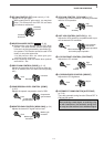
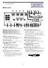
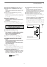
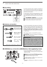
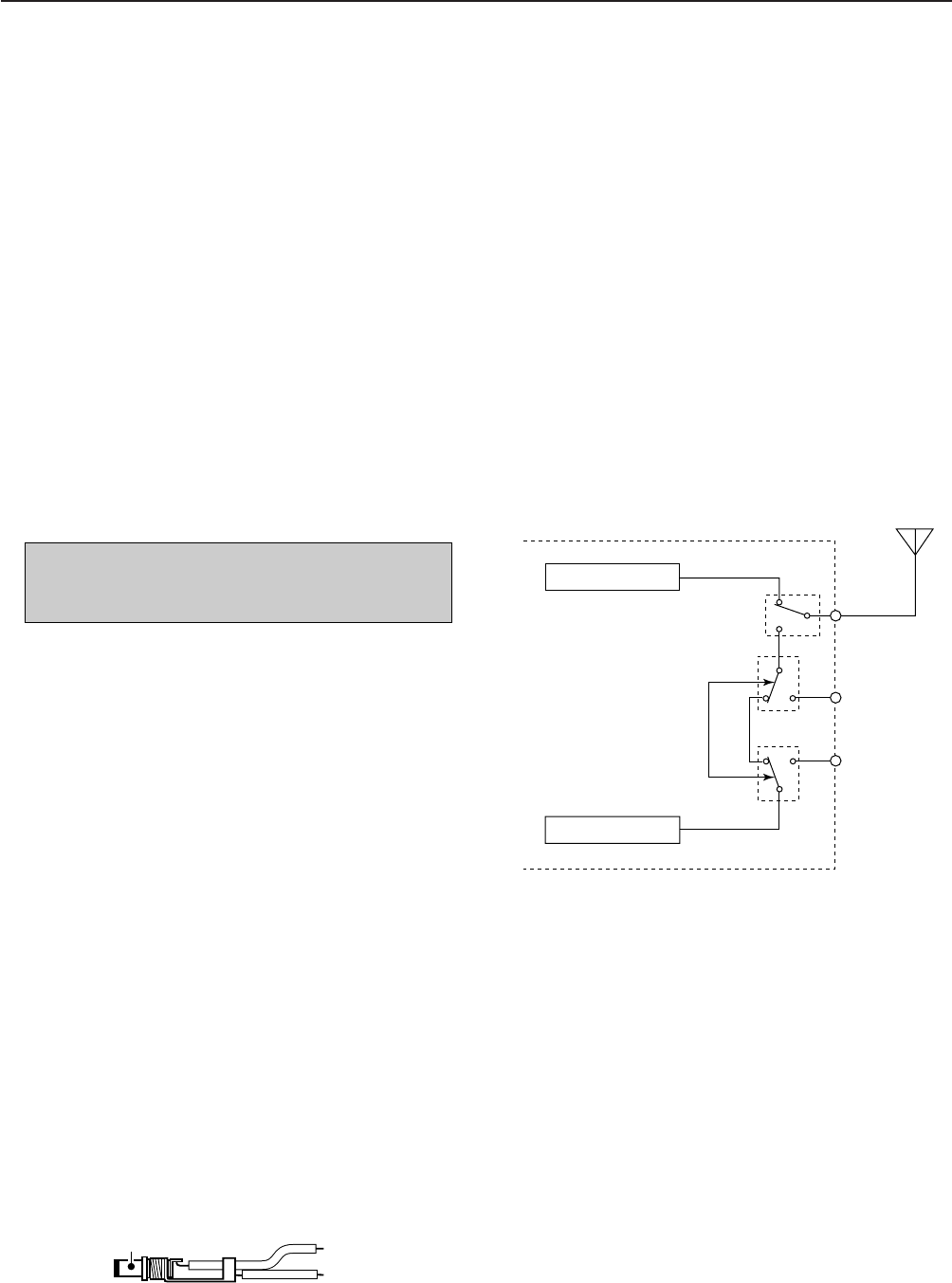
@7 RECEIVE ANTENNA IN [RX ANT– IN]
@8 RECEIVE ANTENNA OUT [RX ANT– OUT]
Located between the transmit/receive switching cir-
cuit and receiver’s RF stage.
Connects an external unit, such as preamplifier or
RF filter, using BNC connectors, if desired.
When no external unit is connected, [RX ANT– IN]
and [RX ANT– OUT] must be deactivated and
shorted by the switching relay internally. This set-
ting is available on the antenna set screen. (p. 10-5)
NOTE: T/R control voltage and current must be
lower than 16 V DC/0.5 A (or 250 V AC,
200 mA with MOSFET switching).
1
PANEL DESCRIPTION
Receiver
Transmitter
IN
[RX ANT]
OUT
Transmit/Receive
switching circuit
+
_
_