


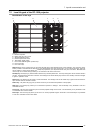

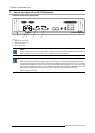


7. Input & communication unit
7.4 About General Purpose Inputs & Outputs (GPIO)
General Purpose inputs
Eight (8) opto-isolated general pur pose inputs are available. These inputs ar e used to trigger the execution of macro files. For mo re
explanation about the association of a macro to a GPI, consult the user guide of the C om mu nicator touch panel.
Input voltage
The inputs can be directly driven from a TTL or CMOS output.
• Minimum voltage : V
min
=3,3V
• Maximum voltage : V
max
=24V
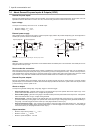
External power supply
When interfacing with contact closure outputs, an external power supply needs to be provided. Depending upon the configuration a
suitable pull-up resistor needs to be added as well.
10k
820R
GPIn P
GPIn P
GPIn N
GPIn N
4.7V
Input to projector Internal projector
1k1
+5V
to
+24V
10k
820R
GPIn P
GPIn P
GPIn N
GPIn N
4.7V
Input to projector Internal projector
1k1
+5V
to
+24V
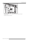
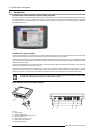
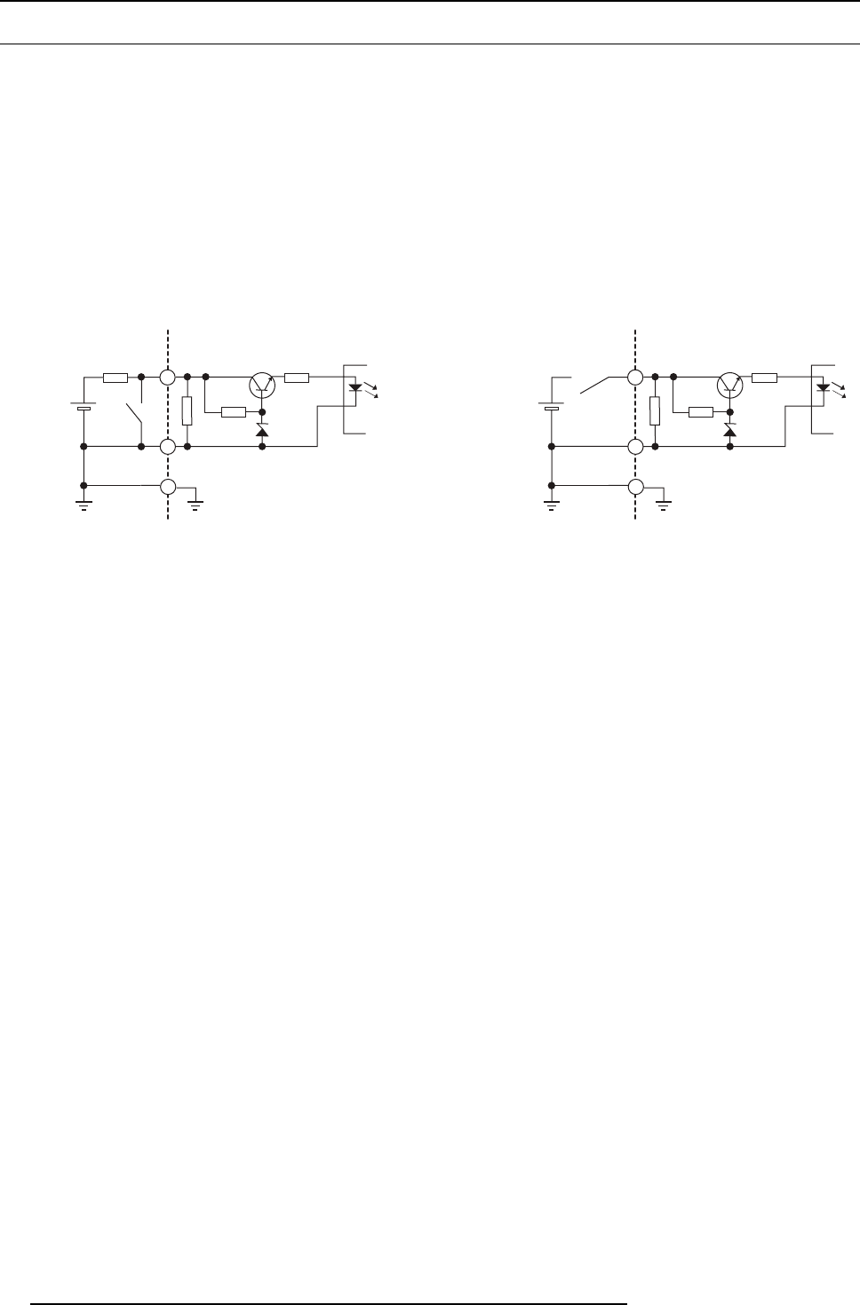
Image 7-4
Left diagram: with pull-up resistor. Right diagram: without pull-up resistor.
Cables
When long cable connections are required the us e of shielded c ables with twisted pairs is recomm ended. One twisted pair is to be
assigned to each GP Input pair.
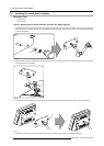
How to make the connection
When the power supply used to pro vide the DC voltage is isolated from ground (for example in the case of a n AC adapter) it is
recommended that minus pole of that power supply is connected to ground (or to the projector chassis). This will avoid high common
mode voltages at the projector GP Inputs. If that same power supply is used for other parts of the system, take care not to create
ground loops. I n any case when shielded cables are used that shield should be connected to the projector chassis.
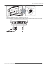
General Purpose outputs
Eight (8) opto-isolated ou tputs are available
, w here seven are gene ral purpose and one for a fix ed purpose. The seven g eneral
purpose outputs can be controlled via software while the fixed output provides the status of the system. When this output is closed
(current is flowing), then the system is OK.
About an output
The output can generate a falling edge, rising edge, toggle or c ontinuous toggle.
• Generate Falling Edge – generate a falling edge on the external G PO port if the present state of the output is high. If the
present state of the external GP O is low, no edge will be generated.
• Generate Rising Edge – generate a rising edge on the external GPO p ort if the present s tate of the output is low. If the present
state of the external GP O is high, no edge wi
ll be gene rated.
• Generate Toggle – generate a toggle on the external GPO port. If the present state of the output is low, a rising edge will be
generated, followed by a falling edge. If the present state of the ou tput is high, a falling e dge will be generated, followed b y a
rising edge. The rate of t oggle will be the vertical sync rate (edge transition at each vsy nc).
• Generate Continuous Toggle - This command w ill generate a continuous toggle of the external GPO port. This toggle will
continue until a Generate Falling Edge, Generate Rising Edge,orGenerate Toggle command is received. The rate of toggle
will be the vertical sync rate (edge transition at each vsync).
Output transistor
• Maximum output driving voltage : V
max
=70V
• Maximum current : I
max
=30mA
• Maximum power dissipation : 120 mW
68
R59770091 DP-1500 06/01/2009