6. Lamp & lamp house
Image 6-14
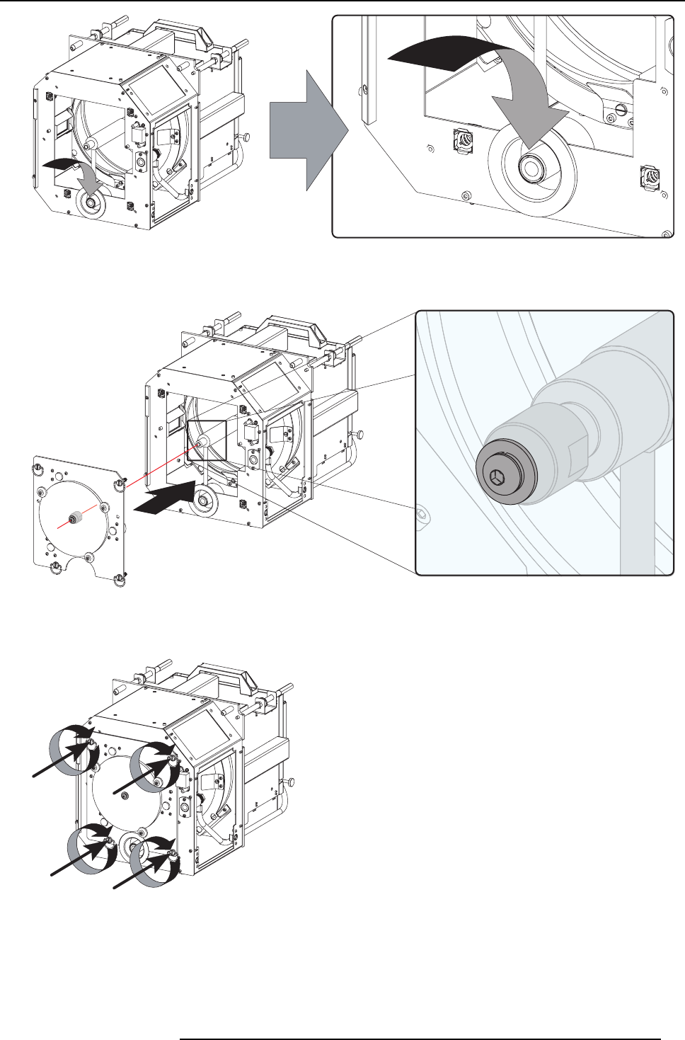
8. Reinstall the UVblocker assembly asillustrated. Make sure that thexenon bulb lampis properly supported bythe lamp supporting
mechanism in the centre of the UV b locker. Us e the opening at the side of the lamp house to guide the supporting pin of the
xenon bulb lamp into the anod e supporting mechanism.
Image 6-15
9. Secure the UV blocker by fastening the four thumbscrews as illustrated.
Note: Please ensure that the thumb screws turning wires are flash with the cover or interference will occur while inserting the
lamp house into the projector.
Image 6-16
10.Fas ten the cathode side of the xenon bulb lam p using a hexagon s ocket hea d screw M6 x 40 and a plane was her as illustrated.
Use a torque of 2,5 Nm to fasten the hexagon socket head screw. U se for that a torque wrench with a 5 mm Allen socket.
Caution: Make sure that the both pins (reference A of image 6-17) of the cathode adapter remain engaged in the foreseen
slots. Therefor, use one hand to keep the xenon bulb lamp into position while inserting the hexagon socket head
screw.
R59770091 DP-1500 06/01/2009
55


