


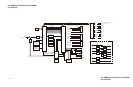

ESG Family Signal Generators Assembly-Level Troubleshooting with Block Diagrams
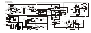
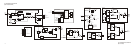
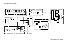
A14 CPU/Motherboard ABUS Nodes
Service Guide 2-41
A14 CPU/Motherboard ABUS Nodes
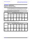
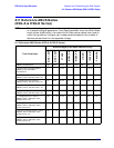
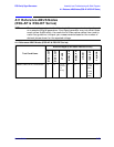
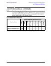
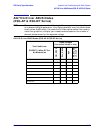
NOTE The node voltages given in the following table are approximate values based
on a sample of signal generators. Your signal generator may not reflect these
exact values. Additionally, the resolution of these values varies from node to
node. As a guideline, interpret your measurements based on the number of
decimal places shown for the expected voltage.
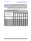
A14 CPU/Motherboard ABUS Nodes
Test Conditions
Node Voltages (Corrected Values in Vdc)
DISP
LCD
INT_MOD
P10V_REF
M6V
M5V
P9V
ACOM
PRESET;
≈7
a
a. Approximately −5.3 V if jumpers for P104, P105, and P106 are set to negative position.
0.00 10 −6.0 −5.2 9.0 0.00
PRESET; Vary Display Brightness 1 to
50
−0.4to
−1.3