


ESG Family Signal Generators Initial Troubleshooting and RF Block Diagrams
Initial Troubleshooting
Service Guide 1-19
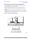
Step 6: Isolate the Failed Assembly
1. Switch off the signal generator.
2. Remove or disconnect an assembly. Below is a suggested order of removal/disconnection
based upon ease.
For the ESG-A and ESG-D Series:
a. A5 Dual Arbitrary Waveform Generator Board (Option UND)
b. A6 Bit Error Rate Test Board (Option UN7)
c. A7 Baseband Generator Board (Options UN3, UN4, UN8, UN9)
d. A8 Data Generator Board (Options UN3, UN4, UN8, UN9)
e. A21 Demodulator Board (Option 300)
f. Front Panel - disconnect A1W1 ribbon cable
g. A3 Inverter - disconnect A3W1
h. A2 Display - disconnect W10
i. AT1 Electronic Attenuator/RPP - disconnect W13
AT1 Mechanical Attenuator and A19 RPP (Option UNB) - disconnect W13 and
A19W1
j. A25 Pulse Modulator (Option 1E6) - disconnect A25W1
k. B1 Fan - disconnect B1W1 (disconnect only temporarily)
l. B2 Fan - disconnect B2W1 (disconnect only temporarily)
m. A9 Output Board
n. A11 Reference Board
o. A12 Synthesizer/Doubler Board
p. A20 YIG Down Convertor Assembly (Option 300) - disconnect W31
NOTE Refer to Chapter 3, “Replaceable Parts (ESG-A and ESG-D Series),” for
information on locating assemblies. Refer to Chapter 5, “Assembly
Replacement,” for information on removing or disconnecting assemblies.
For the ESG-AP and ESG-DP Series:
a. A5 Dual Arbitrary Waveform Generator Board (Option UND)
b. A6 Bit Error Rate Test Board (Option UN7)
c. A7 Baseband Generator Board (Options UN3, UN4, UN8, UN9)
d. A8 Data Generator Board (Options UN3, UN4, UN8, UN9)
e. Front Panel - disconnect A1W1 ribbon cable
f. A3 Inverter - disconnect A3W1