


Assembly Replacement ESG Family Signal Generators
A14 CPU/Motherboard
5-18 Service Guide
A14 CPU/Motherboard
Tools Required
• T-10 TORX screwdriver
• EEPROM extraction tool (Part Number 8710-1982)
Removal
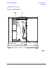
1. Remove the rear panel assembly. (Refer to the “Rear Panel” replacement procedure on
page 5-66 or, if you have Option 1EM, refer to the “Rear Panel (with Option 1EM)”
replacement procedure on page 5-70.)
2. Remove all of the boards in the digital card cage (if installed for your model). (Refer to
the “Digital Card Cage Boards” replacement procedure on page 5-58.)
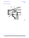
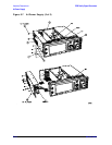
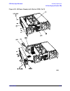
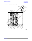
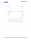
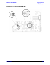
3. Disconnect A1W1, A3W1, A4W1, B1W1, B2W1, W10, and W13 from the
CPU/motherboard (A14). (See Figure 5-10.)
4. Disconnect A14Q501 from the CPU/Motherboard.
If A14Q501 is attached to the back of the CPU/Motherboard (as it is in older models),
this step is not necessary.
5. If you have Option UNB, also disconnect A19W1 from the CPU/motherboard.
If you have Option 1E6, also disconnect A25W1 from the CPU/motherboard.
6. If you have an ESG-A Series or ESG-AP Series signal generator, go to step 7.
If you have an ESG-D Series or ESG-DP Series signal generator, disconnect W25 and
W26 from the CPU/motherboard (A14).
For all current models, disconnect W3, W4, and W5 from the CPU/motherboard,
otherwise go to step 7.
NOTE Figure 5-10 represents an Option UN7/UND.