


Assembly Replacement ESG Family Signal Generators
B1 Small Fan
5-52 Service Guide
B1 Small Fan
Tools Required
• knife blade (or equivalent)
• long nose pliers
Removal
NOTE It is best to attempt this procedure without removing the front panel
assembly. If the front panel assembly is removed, you will be required to
perform time-consuming “Power Level Accuracy” verification tests and
adjustments.
1. Remove the instrument cover. (Refer to the “Instrument Cover” replacement procedure
on page 5-64.)
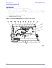
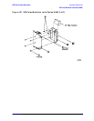
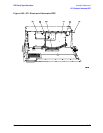
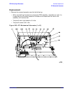
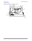
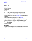
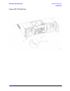
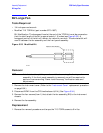
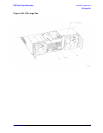
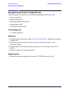
2. Disconnect B1W1 from the CPU/motherboard (A14). (See Figure 5-32.)
3. Remove the four plastic rivets (item 1) that attach the fan assembly (B1) to the
instrument chassis. Use a knife blade (or equivalent) to pry up the head of the plunger
portion of the rivet. Once the head of the plunger is adequately raised, use a pair of long
nose pliers to remove the rivet. Be careful not to damage the rivets with the blade.
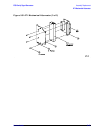
NOTE The plastic rivets consist of two pieces: a plunger and a sheath. Ensure both
parts are removed.
4. Remove the fan assembly.
Replacement
1. Reverse the removal procedure. When reinserting the plastic rivets, the sheath must be
fully seated in the fan assembly before the plunger can be depressed.