


ESG Family Signal Generators Initial Troubleshooting and RF Block Diagrams
Initial Troubleshooting
Service Guide 1-21
Step 7: Check for Basic CPU Functionality
The Digital Signal Processor (DSP) performs a self-diagnostic test at power up. If the DSP
is not working, the CPU reports an error.
If the DSP does not seem to be working and the CPU did not report the error, then check
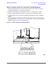
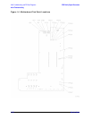
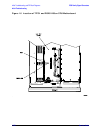
the CLK_OUT signal at TP701. It should be a 16 MHz signal. (Refer to Figure 1-5.)
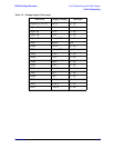
The eight LEDs of DS201 (see Figure 1-5) indicate the status of the boot and flash ROM for
the CPU. The LEDs form a binary code that can be described as a two digit hexadecimal
code. Table 1-4 shows the test sequence and the LED pattern (binary representation) of the
test that is running. If an error occurs and the test is halted, the LED pattern will indicate
which self test halted the process. The LED closest to R201 is the place holder for the Least
Significant Bit (LSB) in the pattern.
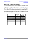
Table 1-4 Sequence for DSP Self-Diagnostic Tests
Test Description
Hexadecimal
Code
Binary
Equivalent
MSB LSB
LEDs at start of test FF 1111 1111
Checksum test FE 1111 1110
Bootrom RAM test FD 1111 1101
RAM test FC 1111 1100
I/O bus test FB 1111 1011
Main firmware checksum test FA 1111 1010
CPU test AA 1010 1010
Test done and OK 00 0000 0000