


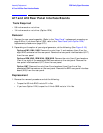


ESG Family Signal Generators Assembly Replacement
A25 Pulse Modulator
Service Guide 5-41
A25 Pulse Modulator
Tools Required
• T-10 TORX screwdriver
• 5/16” open-end wrench
Removal
1. Remove the instrument cover. (Refer to the “Instrument Cover” replacement procedure
on page 5-64.)
2. Remove the top cover by removing the 11 screws that secure it.
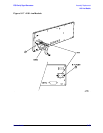
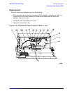
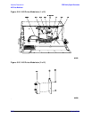
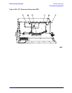
3. Disconnect W45, W46, and W47 from the pulse modulator assembly (A25).
(See Figure 5-24.)
4. Disconnect A25W1 from the CPU/motherboard (A14).
5. Remove the two screws (item 1) holding the pulse modulator assembly to the electronic
attenuator assembly (AT1).
6. Slide the assembly out and up to remove.
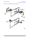
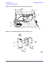
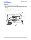
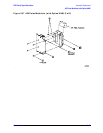
7. Remove the two screws (item 2 in Figure 5-25) that attach the bracket (item 3) to the
pulse modulator.
Replacement
1. Reverse the removal procedure and do the following:
• Torque all screws to 9 in-lbs.
• Torque all semi-rigid cables to 9 in-lbs.