


ESG Family Signal Generators Post-Repair Procedures
Adjustments
Service Guide 6-11
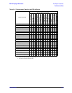
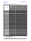
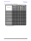
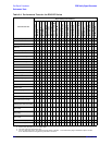
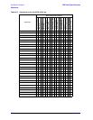
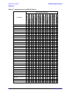
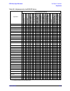
Table 6-8 Adjustments for the ESG-DP Series
Adjustment
Repaired/Replaced Assembly
A1 Front Panel Bd
A2 Display
A2DS1 Lamp
A3 Inverter
A4 Power Supply
A5 Dual Arb Bd
A6 Bit Error Rate Bd
A7 Baseband Gen Bd
A8 Data Gen Bd
A9 Output Bd
A11 Reference Bd
A14 Motherboard
A14BT1 Battery
A15 Daughterboard
A16 Line Module
A17 Rear Panel Bd
A18 BER Rear Pan Bd
A19 RPP
A22 YO Driver
A23 Sampler Bd
A24 Frac-N/Divider Bd
AT1 Elec Atten/RPP
AT1 Mech Atten
ABUS ADC Cal • •
Internal Source Cal •••
VCO Bias Adjustment • • •
Kv vs Frequency Cal •• •
AM Audio Path Offset • • • •
Timebase DAC Cal •••
FM Scale DAC Offset Cal • • •
FM Path Offset Cal •••
FM In-band DAC Offset Cal • • •
FM Invert Amp Offset Cal •••
FM1/2 Path Ratio Gain Cal • • •
Mod Source Relative Gain
Cal
•••
DCFM Cal • • • •
Peak Detector Cal •••
Burst Modulator Cal • • •
LF Output Cal •••
Burst Audio Path Cal • • • •
Prelevel Cal •••
VBLO (Mixer Bias Cal) • • •
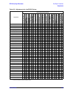
I/Q Gain/Offset Quadrature • •••
Gain Adjust • • • • • •
ALC Adjustments ••• •••
Level Meter Cal • • •
ALC Mod Flatness Cal •••
ALC Mod Driver Bias Cal • • •
AM Audio Path Gain Cal • •••
Power Level Accuracy
•
1
•
1
•
1
•
1
1. Perform this test only if you do not have Option 1EM.
• • • •
•
2
2. Perform this test only if you have Option 1EM.
• • • •
Pretune Calibration •
FM/PM YO Frequency
Calibration
• • •
FM/PM OB Cal ••
LNF Gain Adjust •