


Initial Troubleshooting and RF Block Diagrams ESG Family Signal Generators
Initial Troubleshooting
1-20 Service Guide
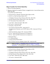
g. A2 Display - disconnect W10
h. AT1 Electronic Attenuator/RPP - disconnect W13
AT1 Mechanical Attenuator and A19 RPP (Option UNB) - disconnect W13 and
A19W1
i. A25 Pulse Modulator (Option 1E6) - disconnect A25W1
j. B1 Fan - disconnect B1W1 (disconnect only temporarily)
k. B2 Fan - disconnect B2W1 (disconnect only temporarily)
l. A9 Output Board
m. A11 Reference Board
n. A23 Sampler Board
o. A24 Frac-N/Divider Board
p. A22 YIG Driver Assembly - disconnect W35
NOTE Refer to Chapter 4, “Replaceable Parts (ESG-AP and ESG-DP Series),” for
information on locating assemblies. Refer to Chapter 5, “Assembly
Replacement,” for information on removing or disconnecting assemblies.
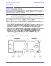
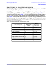
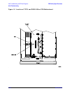
3. Switch on the signal generator and check the voltage supply LEDs (see Figure 1-3). If
the LEDs are lit, you have likely identified the failed assembly. If one or more LEDs are
still off, switch off the signal generator and replace/reconnect the assembly and repeat
this procedure.