


ESG Family Signal Generators Assembly Replacement
A25 Pulse Modulator (with Option UNB)
Service Guide 5-43
A25 Pulse Modulator (with Option UNB)
Tools Required
• T-10 TORX screwdriver
• 5/16” open-end wrench
Removal
1. Remove the instrument cover. (Refer to the “Instrument Cover” replacement procedure
on page 5-64.)
2. Remove the top cover by removing the 11 screws that secure it.
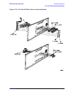
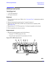
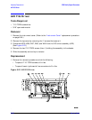
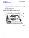
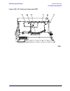
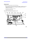
3. Disconnect W45 and W47 from the pulse modulator (A25) and A25W1 from the
CPU/motherboard (A14). (See Figure 5-26.)
4. Disconnect A19W1 from the CPU/motherboard.
5. Disconnect W9 from the RPP (A19).
6. Disconnect W13 from the CPU/motherboard.
7. Remove the two screws (item 1) that attach the attenuator/RPP/pulse assembly to the
instrument chassis.
8. Tilt the assembly away from the chassis wall, then carefully lift it out of the instrument.
NOTE There are two hinged tabs at the bottom of the attenuator/RPP/pulse
assembly that fit into slots in the instrument chassis. Therefore, it is
necessary to tilt the assembly away from the chassis wall so that the tabs can
be guided out of the slots.
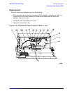
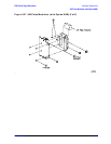
9. Disconnect W20 from the RPP and the mechanical attenuator (AT1).
10.Disconnect W46 from the pulse modulator and the mechanical attenuator.
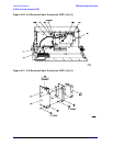
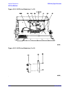
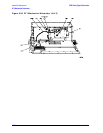
11.Remove the four screws (item 2 in Figure 5-27) that attach the RPP bracket (item 3) to
the attenuator bracket (item 4).
12.Remove the two screws (item 5) that attach the RPP bracket to the pulse modulator.