


Assembly Replacement ESG Family Signal Generators
Rear Panel
5-68 Service Guide
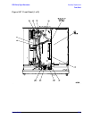
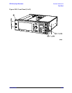
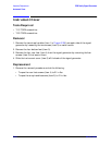
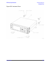
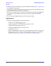
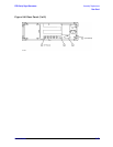
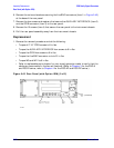
6. Remove the nuts and washers securing the five BNC connectors (item 1 in Figure 5-41)
at the base of the rear panel.
7. Remove the hex screws and washers that secure the AUXILARY INTERFACE (item 2)
and the GPIB connector (item 3) to the rear panel.
8. Remove the 10 screws (item 4) that secure the rear panel to the instrument chassis. Do
not remove the screw that secures the chain and cap for COHERENT CARRIER
connector.
9. Pull the rear panel assembly away from the instrument chassis.
Replacement
1. Reverse the removal procedure and do the following:
• Torque all T-10 TORX screws to 9 in-lbs.
• Torque the AUXILARY INTERFACE hex screws to 6 in-lbs.
• Torque the GPIB hex screws to 9 in-lbs.
• Torque the five BNC connector nuts to 21 in-lbs.
• Torque W12 to 9 in-lbs.
• Refer to replaceable parts chapter for your signal generator model to verify that the
cables are reconnected in the correct locations. (Refer to Chapter 3 for the ESG-A
and ESG-D series, refer to Chapter 4 for the ESG-AP and ESG-DP series.)