


Contents
iii
1. Initial Troubleshooting and RF Block Diagrams
Before You Begin Troubleshooting . . . . . . . . . . . . . . . . . . . . . . . . . . . . . . . . . . . . . . . . . . . . . .1-2
Using this Service Guide to Troubleshoot. . . . . . . . . . . . . . . . . . . . . . . . . . . . . . . . . . . . . . . . .1-2
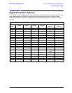
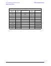
Signal Generator Options . . . . . . . . . . . . . . . . . . . . . . . . . . . . . . . . . . . . . . . . . . . . . . . . . . . . .1-3
Contacting Agilent Technologies . . . . . . . . . . . . . . . . . . . . . . . . . . . . . . . . . . . . . . . . . . . . . . . .1-8
Check the Basics before Contacting Agilent Technologies . . . . . . . . . . . . . . . . . . . . . . . . . .1-8
Review the Warranty . . . . . . . . . . . . . . . . . . . . . . . . . . . . . . . . . . . . . . . . . . . . . . . . . . . . . . .1-8
Calling Agilent Technologies Sales and Service Offices . . . . . . . . . . . . . . . . . . . . . . . . . . . .1-8
Returning Your Signal Generator for Service . . . . . . . . . . . . . . . . . . . . . . . . . . . . . . . . . . .1-10
Equipment Required for Troubleshooting . . . . . . . . . . . . . . . . . . . . . . . . . . . . . . . . . . . . . . .1-11
Initial Troubleshooting . . . . . . . . . . . . . . . . . . . . . . . . . . . . . . . . . . . . . . . . . . . . . . . . . . . . . .1-12
Step 1: Observe the Front and Rear Panel LEDs . . . . . . . . . . . . . . . . . . . . . . . . . . . . . . . .1-12
Step 2: Power On the Signal Generator and Check for Error Messages . . . . . . . . . . . . . .1-13
Step 3: Functional Check the Front Panel Keys and Display . . . . . . . . . . . . . . . . . . . . . .1-14
Step 4: Visually Check the Individual Voltage Supplies. . . . . . . . . . . . . . . . . . . . . . . . . . .1-15
Step 5: Measure the Individual Voltage Supplies . . . . . . . . . . . . . . . . . . . . . . . . . . . . . . . .1-16
Step 6: Isolate the Failed Assembly . . . . . . . . . . . . . . . . . . . . . . . . . . . . . . . . . . . . . . . . . . .1-19
Step 7: Check for Basic CPU Functionality. . . . . . . . . . . . . . . . . . . . . . . . . . . . . . . . . . . . .1-21
Additional Information for Troubleshooting the ESG-AP and ESG-DP Series . . . . . . . . . .1-23
ESG-A Series RF Block Diagram (Standard & Option 1E6) . . . . . . . . . . . . . . . . . . . . . . . . .1-25
ESG-D Series RF Block Diagram . . . . . . . . . . . . . . . . . . . . . . . . . . . . . . . . . . . . . . . . . . . . . .1-27
ESG-D Series RF Block Diagram (Options UN3 & UN4) . . . . . . . . . . . . . . . . . . . . . . . . . . .1-29
ESG-D Series RF Block Diagram (Option UN8 or UN9) Rev C or D . . . . . . . . . . . . . . . . . .1-31
. . . . . . . . . . . . . . . . . . . . . . . . . . . . . . . . . . . . . . . . . . . . . . . . . . . . . . . . . . . . . . . . . . . . . . . . . .1-32
ESG-D Series RF Block Diagram (Options UN8 & UN9) Rev B . . . . . . . . . . . . . . . . . . . . . .1-35
ESG-D Series RF Block Diagram (Option UND) . . . . . . . . . . . . . . . . . . . . . . . . . . . . . . . . . .1-37
ESG-D Series RF Block Diagram (Option UN7, UN8/UN9, & 300) . . . . . . . . . . . . . . . . . . .1-39
ESG-AP Series RF Block Diagram (Standard & Option 1E6) . . . . . . . . . . . . . . . . . . . . . . . .1-41
ESG-DP Series RF Block Diagram . . . . . . . . . . . . . . . . . . . . . . . . . . . . . . . . . . . . . . . . . . . . .1-43
ESG-DP Series RF Block Diagram (Option UN7) . . . . . . . . . . . . . . . . . . . . . . . . . . . . . . . . .1-45
ESG-DP Series RF Block Diagram (Options UN8 & UN9) . . . . . . . . . . . . . . . . . . . . . . . . . .1-47
ESG-DP Series RF Block Diagram (Option UND) . . . . . . . . . . . . . . . . . . . . . . . . . . . . . . . . .1-49
Blue Repair Tags . . . . . . . . . . . . . . . . . . . . . . . . . . . . . . . . . . . . . . . . . . . . . . . . . . . . . . . . . . .1-51
2. Assembly-Level Troubleshooting with Block Diagrams
Before You Begin Troubleshooting . . . . . . . . . . . . . . . . . . . . . . . . . . . . . . . . . . . . . . . . . . . . . .2-2
Using this Chapter with Service Software . . . . . . . . . . . . . . . . . . . . . . . . . . . . . . . . . . . . . . . .2-2
A5 Dual Arbitrary Waveform Generator Block Diagram (Option UND) . . . . . . . . . . . . . . . .2-5
A6 Bit Error Rate Test Block Diagram (Option UN7) . . . . . . . . . . . . . . . . . . . . . . . . . . . . . . .2-7
A7 Baseband Generator Block Diagram (Options UN3 & UN4). . . . . . . . . . . . . . . . . . . . . . .2-9
A7 DBMIC Baseband Generator Block Diagram (Options UN8 & UN9) . . . . . . . . . . . . . . .2-11
A8 Data Generator Block Diagram (Options UN3 & UN4) . . . . . . . . . . . . . . . . . . . . . . . . . .2-13
A8 Data Generator - Rev. A & B Block Diagram (Options UN8 & UN9) . . . . . . . . . . . . . . .2-15
A8 Flex Data Generator - Rev. C & D Block Diagram (Options UN8 & UN9) . . . . . . . . . . .2-17
A9 Output ABUS Nodes (ESG-A Series) . . . . . . . . . . . . . . . . . . . . . . . . . . . . . . . . . . . . . . . .2-19
A9 Output Block Diagram (ESG-A Series) . . . . . . . . . . . . . . . . . . . . . . . . . . . . . . . . . . . . . . .2-21
A9 Output ABUS Nodes (ESG-D Series) . . . . . . . . . . . . . . . . . . . . . . . . . . . . . . . . . . . . . . . .2-23
A9 Output ABUS Nodes (ESG-AP, & ESG-DP Series). . . . . . . . . . . . . . . . . . . . . . . . . . . . . .2-25
A9 Output Block Diagram (ESG-D, ESG-AP, & ESG-DP Series) . . . . . . . . . . . . . . . . . . . . .2-27
A11 Reference ABUS Nodes (ESG-A & ESG-D Series) . . . . . . . . . . . . . . . . . . . . . . . . . . . . .2-29
A11 Reference Block Diagram (ESG-A & ESG-D Series) . . . . . . . . . . . . . . . . . . . . . . . . . . .2-31