


Assembly Replacement ESG Family Signal Generators
Front Panel
5-62 Service Guide
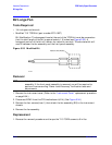
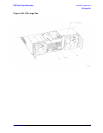
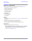
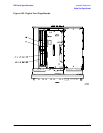
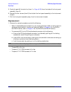
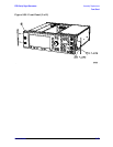
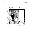
5. Carefully peel off the side trim (item 1 in Figure 5-38) from the sides of the front panel
assembly (item 2).
6. Remove the four screws (item 3) that attach the front panel assembly to the instrument
chassis.
7. Pull the front panel assembly away from the instrument chassis.
Replacement
1. Reverse the removal procedure and do the following:
• Refer to replaceable parts chapter for your signal generator model to verify that the
cables are reconnected in the correct locations. (Refer to Chapter 3 for the ESG-A
and ESG-D series, refer to Chapter 4 for the ESG-AP and ESG-DP series.)
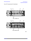
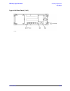
• To reconnect W10 to its CPU/motherboard connector do the following:
a. Ensure the CPU/motherboard connector is unlocked by pulling out the locking
mechanism (much like pulling out a drawer).
b. Insert W10 into the connector, making sure the conductive contacts are facing up
(the blue insulation should be facing down).
c. Lock the connector by pushing in on the locking mechanism.
NOTE Intermittent display problems may result if W10 is not connected correctly.
• Torque W9 to 9 in-lbs.
• Torque all T-10 TORX screws to 9 in-lbs.
• Torque all T-15 TORX screws to 21 in-lbs.