


Assembly Replacement ESG Family Signal Generators
A4 Power Supply
5-12 Service Guide
A4 Power Supply
Tools Required
• T-10 TORX screwdriver
• T-15 TORX screwdriver
Removal
1. Remove the rear panel assembly. (Refer to the “Rear Panel” replacement procedure on
page 5-66.)
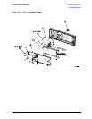
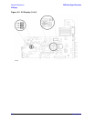
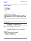
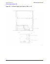
2. Remove the screw (item 1 in Figure 5-6) that attaches the CPU/motherboard (A14) to
the bottom of the power supply shield (item 2).
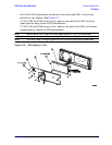
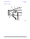
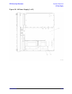
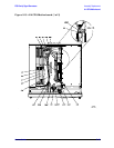
3. Disconnect A4W1 from the CPU/motherboard (A14). (See Figure 5-7 on page 5-14.)
4. Carefully peel off the side trim (item 3) from the left side of the front panel assembly
(item 4).
5. Remove the two screws (item 5) that attach the power supply shield (item 2) to the front
panel assembly.
6. Remove the five screws (item 6) that attach the power supply shield to the instrument
chassis (item 7).
7. Lift the rear of the power supply shield one-quarter inch and then pull it away from the
instrument chassis.
NOTE While removing the power supply shield, try to limit the movement of the
front panel assembly. This will reduce the stress on W9.
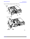
8. Remove the 12 screws (item 8) that attach the power supply to the power supply shield.
9. Remove the power supply (A4) from the front end of the shield.
NOTE Before proceeding to the next step ensure that the instrument is fully
supported on a flat surface. This will keep the front panel assembly stable
during the time it is attached only to the right side of the instrument.
Replacement
1. Reverse the removal procedure and do the following:
• Torque all T-10 TORX screws to 9 in-lbs.
• Torque all T-15 TORX screws to 21 in-lbs.