


Installation TANDBERG Director Videoconferencing System
26
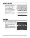
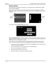
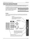
Network Connections
The network connections are located on the rear interface panel of the TANDBERG 6000 Codec.
The network cables should be connected as applicable to the site. Refer to ‘ADVANCED USE’ >
‘TERMINAL SETTINGS’ for more information concerning IP settings and other network equipment
that may be required, such as network terminating units and CSUs.
ISDN BRI
Connect each ISDN cable to the ISDN BRI sockets found on the codec. Then connect the other
end of the loom to the appropriate wall sockets. If however, the wall sockets provide an ISDN U-
interface, the ISDN lines from the codec must first be connected to the S/T interface of network
terminating units NT1 and NT384. Then connect the U interface of the network terminating units to
the wall sockets.
ISDN PRI/T1
Connect the PRI/T1 cable to the PRI/T1 socket labeled “1” on the codec. Connect the other end of
the cable to a Channel Service Unit (CSU). Then connect the CSU to the site’s PRI/T1 line.
Other Networks - Using the External Network Interface
If you are using other networks, please refer to ‘EXTERNAL NETWORK SETTINGS’ and ‘APPENDIX 2’.
LAN
Connect the LAN cable from the LAN connector on the rear of the codec to the site’s LAN network
connection.
It is recommended that both the codec and control system be provided with a LAN connection.
The system will function without a LAN connection if you are placing ISDN calls only, but a LAN
connection is recommended for both software upgrades and remote diagnostics. The control
system LAN information must be set locally. For information regarding the network settings on the
codec, refer to ‘ADVANCED USE’ > ‘TERMINAL SETTINGS’.
NOTE
THE LAN CONNECTION ENABLES
YOU
TO PLACE IP CALLS ONLY,
SOFTWARE UPGRADES AND
REMOTE
DIAGNOSTICS. ISDN
CALLS MUST HAVE ISDN
CONNECTIONS CONFIGURED.
NOTE
BE SURE TO WRITE DOWN THE
NUMBERS
ASSOCIATED WITH EACH
OF
THE ISDN LINES. YOU WILL
NEED
THEM LATER TO CONFIGURE
THE SYSTEM.