


System Overview
Runco SC-30d/SC-35d Installation/Operation Manual 11
PRE
L
IMINAR
Y
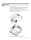
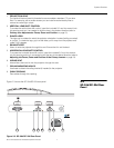
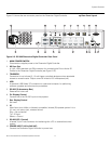
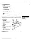
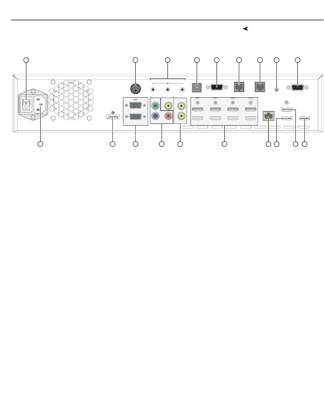
Rear Panel LayoutFigure 2-5 shows the rear connector panel on the Dimension Digital Controller.
Figure 2-5. DC-300 Dimension Digital Controller Rear Panel
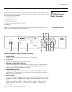
1. MAIN POWER SWITCH
Disconnects or applies power to the Dimension Digital Controller.
2. 3D Sync Out
A 3-pin, VESA standard mini-DIN connector for connecting the Runco Active 3D
Emitter to the Dimension Digital Controller (see Figure 3-25).
3. TRIGGERS
Connection for up to three (3), 12-volt trigger-controlled devices such as retractable
screens or screen masks. Output current is limited to 250 milliamperes (mA).
4. USB
A standard, USB Series “B” connection to a personal computer, for performing
software upgrades and other service procedures.
5. RS-232 (To Accessory Box)
Reserved for future use.
6. Pri. Display Control
Connect this to the RS-232 input on the projector.
7. Sec. Display Control
Not used.
8. IR
Wired input from a Niles- or Xantech-compatible, infrared (IR) repeater system. It is a
3.5-mm, mini phono jack, wired as follows:
Ring = No connection
Tip = IR Input
Sleeve = Ground
9. RS-232 (PC / Control)
A female, 9-pin D-sub connector for interfacing with a PC or automation/control
system.
10. POWER INPUT (100 to 240 VAC)
Connect the Dimension Digital Controller to power here.
USB
To Accessory Box
Video 1
Y
Video 2
Video 3
Pr
Pb
PC / Control
RS-232
IR
Pri. Display Control Sec. Display Control
HDMI 2 HDMI 4 HDMI 6 HDMI 8
Ethernet
HDMI Out
To Sec. Display
HDMI Out
To Pri. Display
HDMI Out
Audio Only
Component / SCART
TRIGGERS
RS-232
123
3D SYNC
HD2
DisplayPort
Y
P
r
P
b
Compone
1916
11
10
8
3
96 754
H
D
2
12
13 181714
Vi
deo
1
Vi
d
eo
2
Vi
deo
3
ent / SCAR
T
ne
1 2
HDMI
2
HDMI
4
HDMI
6
HDMI
8
15