


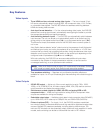
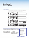
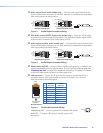
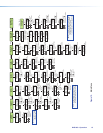
i Audio output (fixed, audio models only) — Connect audio output devices to this
5‑pole, captive screw connector for line level, balanced or unbalanced, analog stereo.
Wire the connectors as shown below.
Balanced Audio Output
Tip
Ring
Tip
Ring
Sleeves
Unbalanced Audio Output
Tip
No Ground Here
No Ground Here
Tip
Sleeves
LR
LR
Do not tin the wires!
Figure 4. Audio Output Connector Wiring
j RCA audio output (S/PDIF, fixed, audio models only) — Plug in an S/PDIF audio
output device into this female RCA connector. This connector outputs digital S/PDIF
audio formats (2‑channel LPCM, Dolby Digital, or DTS).
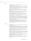
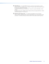
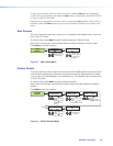
k Audio output (variable, audio models only) — Connect audio output devices to this
5‑pole, captive screw connector for line level, balanced or unbalanced, analog stereo.
Wire the connectors as shown below.
Balanced Audio Output
Tip
Ring
Tip
Ring
Sleeves
Unbalanced Audio Output
Tip
No Ground Here
No Ground Here
Tip
Sleeves
LR
LR
Do not tin the wires!
Figure 5. Audio Output Connector Wiring
l Reset button and LED — Using an Extron Tweeker, pointed stylus, or ballpoint pen,
press this recessed button for manual resets. The unit has four modes of reset (see
“Resetting the Unit” on page 33 for additional information). The green LED flashes
to show the reset mode indications and that power is on.
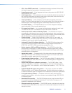
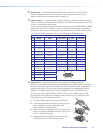
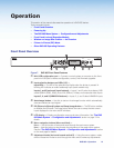
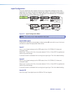
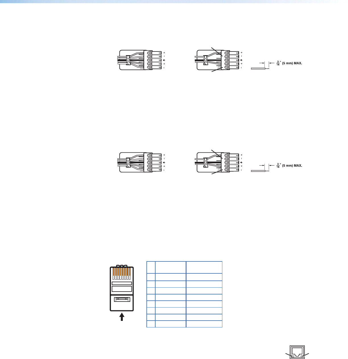
m LAN connector — Plug an RJ‑45 jack into this socket to connect the unit to a
computer network. Use a patch cable to connect to a switch, hub, or router.
Wire the connector as shown below.
12345678
RJ-45 Connector
Insert Twisted
Pair Wires
Pins:
Pin
1
2
3
4
5
6
7
8
Wire color
White-green
Green
White-orange
Blue
White-blue
Orange
White-brown
Brown
Wire color
T568A T568B
White-orange
Orange
White-green
Blue
White-blue
Green
White-brown
Brown
Figure 6. RJ-45 LAN Connector Wiring
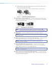
LAN Activity LED — A blinking yellow LED indicates LAN activity.
Link LED — The green LED lights to indicate a good LAN
connection.
LAN
Activity
Link
DVS 605 • Rear Panel Connections 10