


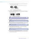
5. While holding the connector securely against the lacing bracket, tighten the tie
wrap, then remove any excess length.
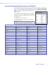
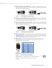
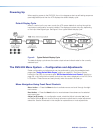
The LockIt bracket can also be used in a stacked formation, as shown below.
Side Mounted
Stacked
Figure 2. LockIt Bracket Mounting Options
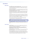
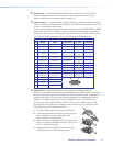
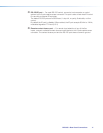
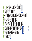
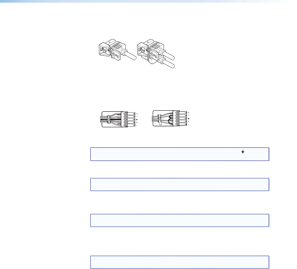
d Audio inputs 1-5 (audio models only) — Connect audio sources to these 5‑pole
captive screw connectors. Wire the connector for line level, balanced or unbalanced,
analog stereo as shown below.
Balanced Stereo Input
Tip
Ring
Tip
Ring
Sleeves
LR
Unbalanced Stereo Input
Tip
Sleeve
Sleeve
Tip
LR
Figure 3. Audio Input Connector Wiring
NOTE: Control signal ground pins are labeled “G”. Audio ground pins are as .
The wiring and function are the same, whichever way your product is labeled.
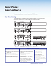
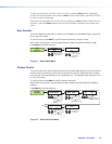
e HDMI output — Connect an HDMI display device to this HDMI connector.
NOTE: All video outputs (HDMI, VGA, SDI) share a common output resolution and display
the same content.
f RGB or HD component (R-Y, Y, B-Y) 15-pin HD video output — Connect an RGB
video display or HD component video display to this HD 15‑pin connector.
NOTE: Simultaneous identical scaled outputs for HDMI and analog RGB or HD
component video are available.
g Optional 3G-SDI/HD-SDI output connector — Connect an SDI (serial digital
interface) display to this female BNC connector for SDI output. This complies with
SMPTE 292M and 424M and ITU video digital standards.
NOTE: 3G/HD‑SDI output is only active if the current resolution is set to 720p, 1080i,
1080p, or 2k 23.98/24/25 hz.
h Genlock connector and loop through (SDI models only) — Connect an external
reference signal for synchronization of the SDI output. The loop through can be used
to synchronize additional devices.
DVS 605 • Rear Panel Connections 9