


91
Chaper 4 Operation Tips
Chapter 4 Operation Tips
Basic Operation Procedure
Basic Mixer Operation Flow from Turning On to Monitoring
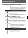
The basic mixer operation is explained in the following operation flow
chart.
Example: In the following flow chart, audio from the microphone
connected to the IN A connector is routed to CH 1 and the fader is used as
a channel fader. Then the signal is output to the PGM bus and monitored
on the control monitor. The unit is used in manual mode.
For detailed information on operations, see the page in parentheses.
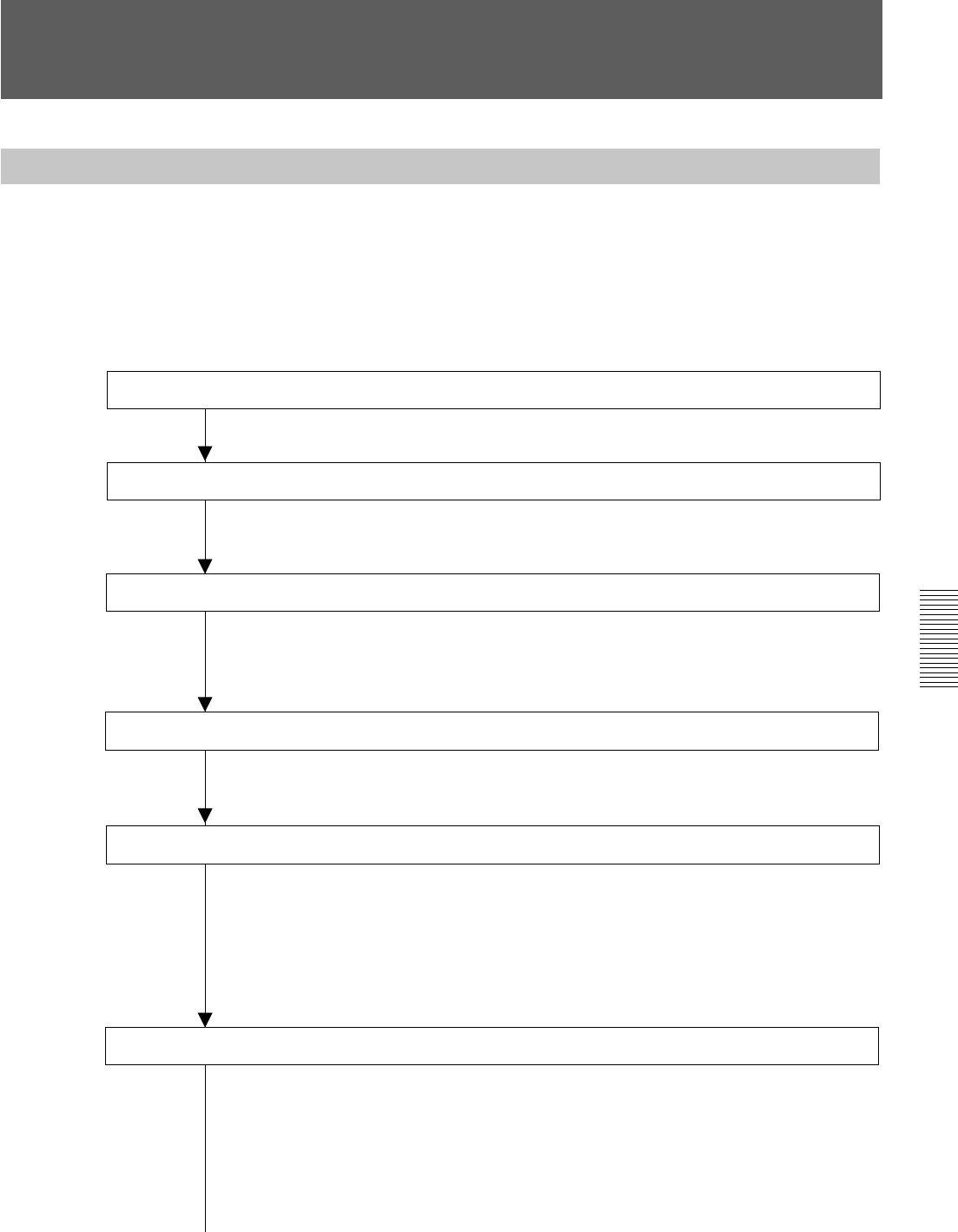
Turning on the power
The unit starts after 1 minute.
Loading the existing title or creating a new title.
On the TITLE MANAGER window (page 72), you can create a new title
or load the existing title.
Confirming/changing the sampling frequency and timecode
On the SYNC/TIME CODE window (page 76), confirm the sampling
frequency, the source of the synchronous signal, and the timecode mode.
If they are not set to the desired settings, change the settings.
Disabling automation operation
• Press the TC LINK button on the Automation panel (page 25) to OFF.
• Press the AUTOMATION OFF button so it is lit (i.e. off).
Routing the input signal
Confirm that AD 1 is routed to CH 1 on the AUDIO INPUT ROUTING
window (page 55).
Also, you can select AD 1 from the list of the input sources on the
SOURCE section of the INPUT section on the INPUT/PAN/ASSIGN
window (page 44).
(Change the audio input routing as required.)
Routing the output signal
Confirm that the PGM bus is routed to the PGM output connector on the
AUDIO OUTPUT ROUTING window (page 57).
(Change the audio output routing as required.)
To the next page