


29
Chapter 2 Locations and Functions of Parts and Controls
Chapter 2 Locations and Functions of Parts and Controls
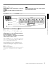
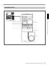
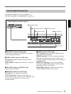
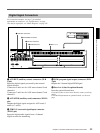
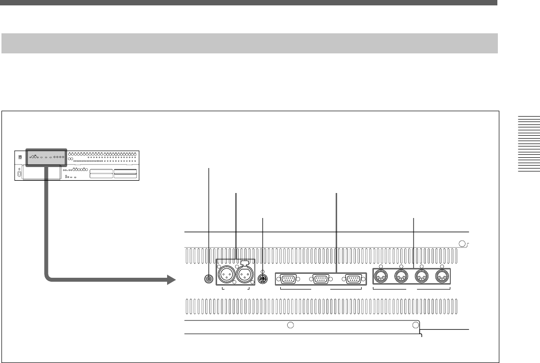
Control Signal Connectors
FOOT SW TIME CODE PC PORT REMOTE
OUT 1
THRU OUT IN MTC
PUSH
OUT 2 IN
MIDI
1 FOOT SW connector
2 TIME CODE connectors
3 PC PORT connector
4 REMOTE connectors
5 MIDI connectors
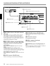
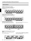
1 FOOT SW connector (Phone jack)
Connect the foot switch (not supplied) to control the
remote automation functions.
2 TIME CODE connectors (XLR 3-pin)
IN connector: Inputs the timecode signal from an
external device.
OUT connector: Outputs the timecode to an external
device.
3 PC PORT connector (Mini DIN 8-pin)
Connect the host computer.
4 REMOTE connectors (D-sub 9-pin)
IN connector: For expansion use in future.
OUT 1/2 connectors: Used for connecting to an
external device such as VTR. You can control the 9-pin
devices using the transport control keys on the
automation panel.
Control signal connectors (part 1)
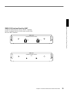
5 MIDI connectors (DIN 5-pin)
MTC connector: Inputs the MTC (MIDI timecode)
used in automation operation.
MIDI IN connector: Used for connecting incoming
MIDI data, including remote control of faders, pan,
cuts and snapshots, functions depend on the settings of
the MIDI window.
MIDI OUT connector: Used for outgoing MIDI
messages, including MIDI machine control and front
panel tallies (faders, cuts and pan).
MIDI THRU connector: Outputs the signal input
from the MIDI IN connector via a buffer.
For connection examples, see page 7, for detailed
information on connectors, see “Specifications” on page
110, and for signal flow, see “Block Diagram” on page 121.