


31
Chapter 2 Locations and Functions of Parts and Controls
Chapter 2 Locations and Functions of Parts and Controls
13
12 11 10 9 8 7 6 5 4 3 2 1
PUSHPUSHPUSHPUSHPUSHPUSHPUSHPUSHPUSHPUSHPUSHPUSH
12 11 10 91 87654321
12 11 10 9 8 71 654321
INSERTION
IN B
IN A
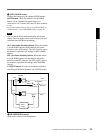
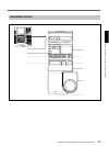
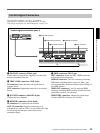
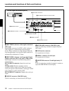
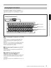
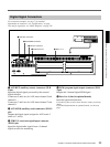
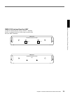
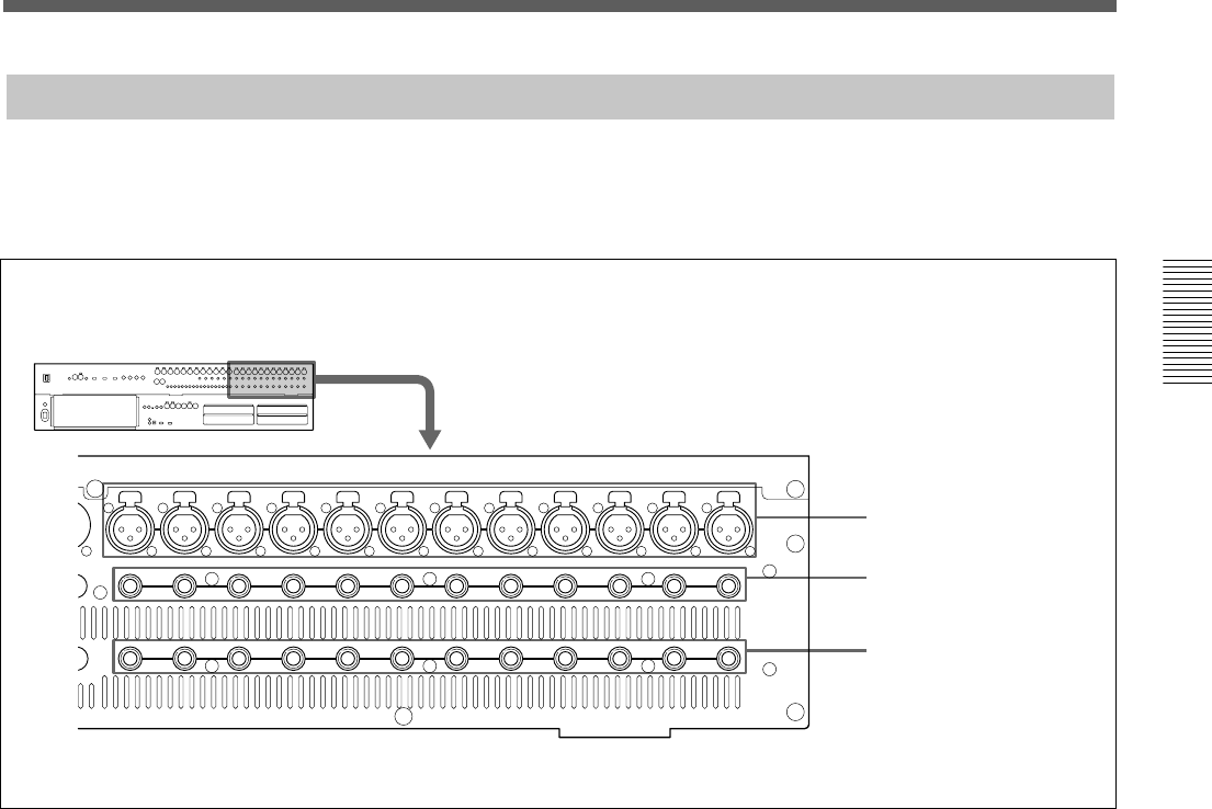
Analog Signal Connectors
1 IN A connectors
2 IN B connectors
3 INSERTION connectors
1 IN A (analog input A) connectors 1 to 12 (XLR
3-pin)
These connectors are enabled when the INPUT B
button on the analog head amplifier panel is not
pressed.
The IN A 1 to 12 connectors are equipped with 48 V
power for condenser microphones, each channel
feature a front panel 48 V switch
2 IN B (analog input B) connectors 1 to 12 (1/4”
TRS jack)
These connectors are enabled when the INPUT B
button is pressed.
3 INSERTION (insertion input/output)
connectors 1 to 12 (1/4” TRS jack)
Used for connecting external effectors the inserts are
analog and positioned before the analog to digital
converters.
For the pin assignment of the INSERTION connectors, see
page 111.
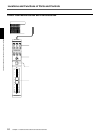
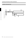
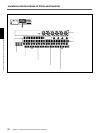
Analog Connectors (part 1)
For connection examples, see page 7, for detailed
information on connectors, see “Specifications” on page
110, and for signal flow, see “Block Diagram” on page
121.