


33
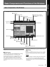
Chapter 2 Locations and Functions of Parts and Controls
Chapter 2 Locations and Functions of Parts and Controls
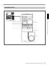
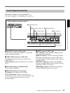
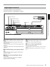
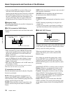
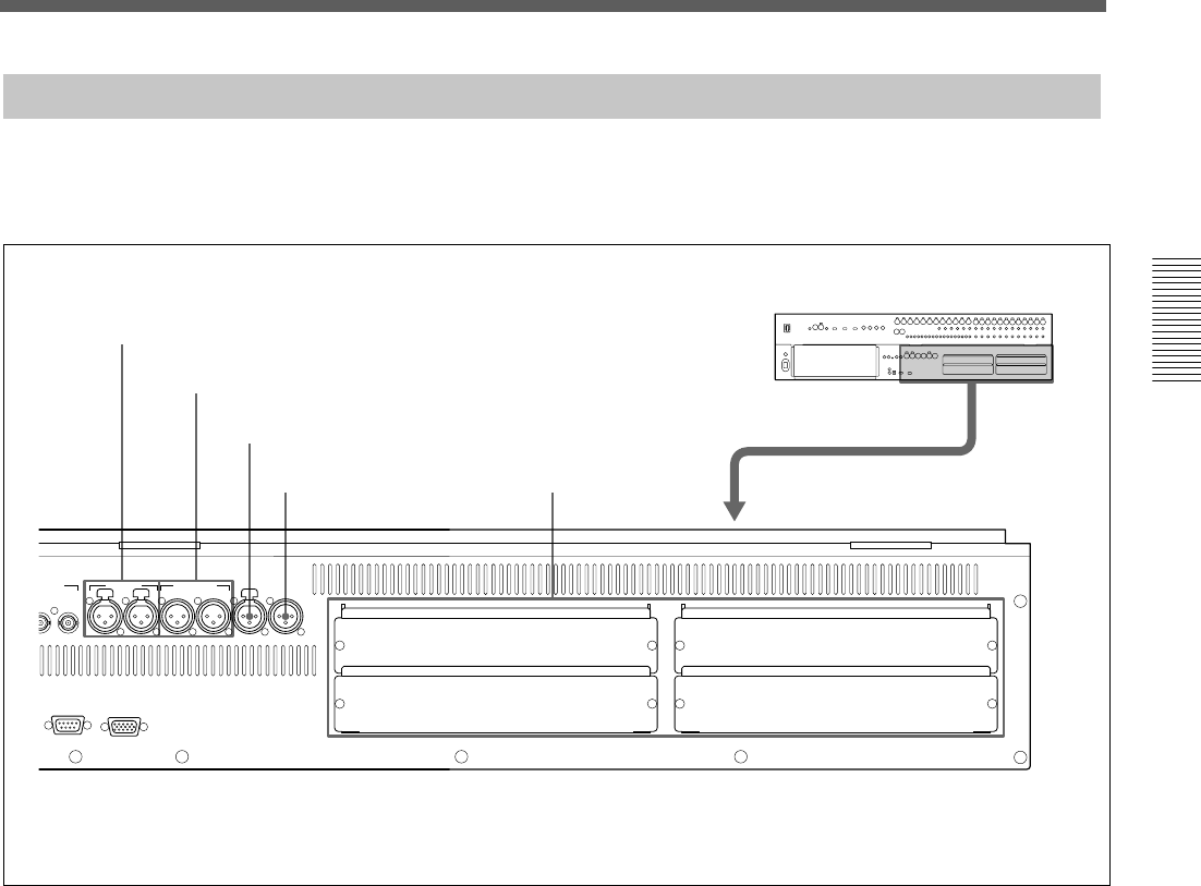
Digital Signal Connectors
SLOT 2
SLOT 4
SLOT 1
SLOT 3
PUSHPUSH PUSH
SERIAL MONITOR
WORD AUX RET AUX SEND 2TR IN2 PGM
N
7/8 5/6 7/8 5/6
OUT
1 AUX RET connectors
2 AUX SEND connectors
3 2TR IN 2 connector
4 PGM connector
5 Slots 1 to 4
For connection examples, see page 7, for detailed
information on connectors, see “Specifications” on page
110, and for signal flow, see “Block Diagram” on page 121.
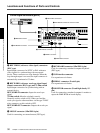
1 AUX RET (auxiliary return) connectors (XLR
3-pin)
Inputs the digital signals processed by the external
digital effectors.
Connectors 5 and 6 are for AUX-return channel 5 and
channel 6.
Connectors 7 and 8 are for AUX-return channel 7 and
channel 8.
2 AUX SEND (auxiliary send) connectors (XLR 3-
pin)
Outputs the digital signals assigned to AUX sends 5
and 6 (or 7 and 8).
3 2TR IN 2 (two-track signal input) connector
(XLR 3-pin)
Inputs the digital audio signals from a 2-channel
digital recorder for monitoring.
4 PGM (program signal output) connector (XLR
3-pin)
Outputs the 2-channel digital PGM signal.
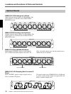
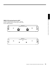
5 Slots 1 to 4 (slots for optional boards)
Insert the optional boards here.
For details of how to insert these boards, contact your Sony
dealer.
For detailed information on optional boards, see the next
page.