


RC3000 Antenna Controller Chapter 3 Detailed Operation
83
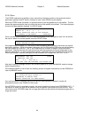
3.2.2.3.5 Terminal Peak Up
NOTE: this option is only functional if the mount has been fitted with high resolution pulse or
resolver sensors for both the azimuth and elevation axes. This option will not be available on
some mounts where the ability to fit high resolution sensors is not available. The performance of
this movement depends on whether or not the correct azimuth and elevation pulse scale factors
(3.3.1.3.3 and 3.3.1.3.6) have been characterized for the mount.
The terminal peakup option is selected via the AUTOPEAK ON configuration item (3.3.1.2.6).
If an azimuth scan finds a peak, it will return to the azimuth position where it noted the peak. This
position may not be the absolute peak position due to the relatively large steps taken during the azimuth
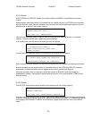
scan. If enabled, the terminal peakup option will next perform a “fine tune” peakup. While executing this
peakup, line 4 will display “PERFORMING PEAKUP” and the AZIM and ELEV fields will display pulse or
resolver counts rather than angles.
During the peakup, small jogs in azimuth and elevation will be made to find the local peak position.
These movements will be similar to the Step Track maneuver described in 3.2.2.9.1. The step sizes
taken will approximate a theoretical signal strength change of 0.3 dB (according to antenna size,
operating band, etc).
3.2.2.3.6 Polarization Tilt Compensation
If enabled via the TILT configuration item in the AUTOPEAK screen (3.3.1.2.6), additional movements in
azimuth will be made during the LOCATE function in order to characterize the pitch and roll of the
antenna platform.
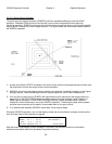
Rather than going directly to the beginning point for a scan operation, azimuth will be moved to points 90
and 45 degrees away. The elevation axis will not be changed during these moves so the effect of
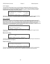
platform pitch and roll can be measured via the inclinometer. During these additional azimuth
movements a message such as "DETERMINE TILT: MOVE AZIM TO FIRST POINT" will be displayed on
line 4 to indicate that the tilt is being characterized.
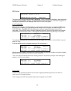
After the platform tilt has been characterized, the normal LOCATE sequence will be finished. After
reaching the target location, an additional step will be performed to move polarization to compensate for
any platform tilt. During this step the message "ADJUSTING POL TO COMPENSATE FOR TILT" will be
displayed.