


RC3000 Antenna Controller Chapter 2 Installation
59
Adjusting the gain of the AGC channel in step 7 will modify the offset voltage in step 6. Steps 6 and 7
should be run at least twice and possibly several times until the required adjustments are minimal.
NOTE: When correctly adjusted, the displayed signal strength will be approximately 50 when “off”
the satellite and approximately 650 when “on” the satellite. These values allow for conditions
when the signal strength may be stronger than they were at the time of adjustement.
Step 8. Set Thresholds
Having observed the displayed value for signal strength, the user should set the autopeak threshold
(3.3.1.2.6) and SS1/SS2 thresholds (3.3.1.2.5) for correct operation of autopeak and tracking operations.
The signal strength system is now adjusted correctly for use by the autopeak and tracking functions. A
common situation affecting signal strength measurement performance is discussed next.
2.4.3.4 Amplifier Gain vs. Frequency Characterization
An amplifier's gain vs. frequency characteristic, or gain flatness, is the variation of the amplifier's gain with
changing frequency. The ideal response is to have a flat gain characteristic (the gain does not vary with
frequency). Amplifiers with poor gain flatness characteristics can cause problems for the tracker. This
section describes a simple test (no equipment required) that the user can carry out to check the receiving
system's gain flatness.
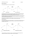
There are four places in a satellite receiving system that may have gain flatness problems that can affect
the operation of the tracker. These are the LNB, the coaxial cable connecting the LNB to the receiver,
line amps (or bullet amps) inserted in the 950 - 1750 MHz IF, and the receiver's IF or AGC stages. If a
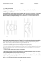
spectrum analyzer is connected into the receiver's block IF line, the gain flatness of the LNB and any line
amps present can be observed. When the antenna is pointed away from any satellite, the spectrum
analyzer displays the received noise, which should be constant with frequency. If the display is not a
horizontal line then some gain variation with frequency is present.
To understand how a poor gain flatness characteristic can cause problems, remember that the purpose
of the signal strength input is to let the controller determine whether a satellite signal is present or not,
and to provide relative signal strength information when peaking the antenna. A signal is assumed to be
present whenever the input is above the threshold level for whichever band has been selected. When the
receiver is tuned to various transponders, gain flatness problems could cause the signal to be above the
threshold, when in fact no satellite signal is present. For certain transponders, gain flatness problems
could also cause the controller's input scaling network to be saturated when the antenna is aligned with a
strong satellite, making it impossible for the controller to detect changes in signal strength when
attempting to peak the antenna.
To test the gain flatness of the satellite receiver, perform the following procedure. The procedure
assumes a single receiver, single frequency band system.
1. Position the antenna well off of any satellite. Tune the receiver to each transponder. Make sure that
the signal strength reading is below the threshold assigned via CONFIG mode.
2. Align the antenna with a strong satellite. Tune the receiver to each active transponder on the satellite.
Make sure that the signal strength is well above the threshold and below 999.
If the system fails either of the tests above, then the user can either attempt to correct the problem by
readjusting the GAIN and OFFSET pots (using the procedure outlined earlier), or by correcting the gain
flatness problem. Most gain flatness problems can be traced to a problem with the coaxial cable
connecting the antenna to the receiver (sometimes called a 'suck-out') or to bullet amplifiers. Some bullet
amplifiers have been observed to have terrible gain flatness characteristics.