


RC3000 Antenna Controller Chapter 2 Installation
44
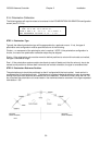
STEP 3a. – Inclinometer Reference Voltage
To perform this step, raise the antenna until the reflector is in the reference position appropriate for this
mount (see Appendix B). For the majority of mounts, the reference position corresponds to having the
reflector’s face vertical. This angle can be confirmed by use of a level or digital inclinometer placed on a
correct portion of the antenna structure.
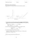
The elevation voltage shown on the AD VOLTAGES screen (3.3.2.1) should be near the target value for
your mount as noted in appendix B. For the majority of mounts, this target voltage will be around 1.69
volts. This voltage allows for the greatest range of linear feedback from the elevation inclinometer
throughout the mount’s operational range. If not, loosen the elevation sense restraining plate and rotate
the inclinometer until the elevation voltage is as near to the target voltage as possible. Secure the
restraining plate and record the voltage.
Recorded Elevation Reference Voltage ______________V
Move to the Elevation Calibration configuration screen and enter the recorded value in the REF_V item.
This will define to the RC3000’s software the voltage that should be seen when the elevation axis is in its
reference position. To verify that data has been entered correctly, return to the MANUAL mode screen.
The displayed elevation angle should be near the RF look angle offset of the reflector (see appendix B).
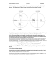
STEP 3b. Elevation Resolver Reference
NOTE: this step only needs to be performed for those mounts that incorporate a resolver sensor
on the elevation axis.
This step should be performed at the same elevation axis position as in step 3a. Additionally, the
vehicle/platform should be level since the resolver will not compensate for tilt as the inclinometer does.
Rotate the elevation resolver until a raw resolver angle of approximately 180.0 degrees in seen in the
MAINTENANCE-VOLTS screen. Lock the elevation resolver in place and observe the raw resolver
angle. Subtract this observed angle from the reflector’s RF angle and enter it as the elevation resolver
offset (see 3.3.1.2.2).
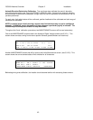
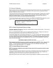
EXAMPLE
Raw resolver angle at elevation reference position: 179.2
Reflector’s RF angle at elevation reference position: 22.3
Required elevation resolver offset: -156.9 ( 22.3 – 179.2)
NOTE: on mounts equipped with an elevation resolver sensor, the elevation angle displayed when below
the DOWN limit is derived from the resolver not the inclinometer. To perform a “sanity check” of the
resolver calibration, move the reflector up and down around the point that the DOWN limit occurs. With
the vehicle/platform level there should be very little discernable jump in the displayed elevation angle.