


RC3000 Antenna Controller Chapter 3 Detailed Operation
111
3.3.1.3.4 Azimuth Drive Monitoring
The items on this screen deal with the background checking performed on the azimuth drive system.
Note that in this context “slop” may be typically considered relating to mechanical hysteresis.
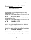
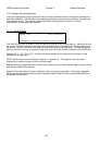
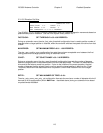
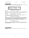
CONFIG-AZ MON
JAM SLOP: 1 FAST DEADBAND: 1000
RUN SLOP: 50 SLOW DEADBAND: 500
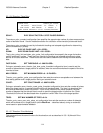
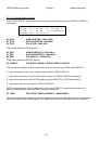
SET JAM SLOP <0 - 1023>
JAM SLOP: SET JAM SLOP <0 - 1023>
The azim_jam_pot_slop item specifies the amount of sensed movement the controller wants to see
before declaring a jam condition. See the Drive System theory section.
The entered value is in units of the resolution the RC3000’s analog to digital conversion system. This
resolution will depend on a particular mount’s range of movement, etc. See appendix B for details for a
particular mount.
The value should be set to avoid nuisance jams but allow a jam to be declared within a reasonable
amount of time to avoid damage to the system. Too high of a value will trigger false jam conditions since
the mount may sometimes not be able to move that far in the required interval. Too low of a value may
allow mechanical slop in the system to appear as valid movement thus never triggering a jam.
Setting the value to 0 will disable the jam sensing since no movement will be required to be sensed to
make the jam system think the mount has moved when it should. This may be a useful thing to do in
emergency situations to alleviate unwanted jam declarations but should only be done temporarily vs.
having an active jam sensing system.
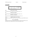
RUN SLOP: SET RUNAWAY SLOP <0-1023>
The azim_runaway_pot_slop item specifies the amount of movement that may be sensed before a
runaway condition is declared when the antenna is not supposed to be moving.
The entered value is in units of the resolution the RC3000’s analog to digital conversion system. This
resolution will depend on a particular mount’s range of movement, etc. See appendix B for details for a
particular mount. If the installation has pulse-based sensing this value will indicate the number of pulses
the system may see before declaring a runaway.
If the entered value is too low, normal noise from the potentiometer or slight movement due to wind may
trigger a runaway. If the value is too high, it may take a long time to generate a runaway. To essentially
disable runaway sensing, set the value to 1023.
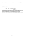
FAST DEADBAND: SET FAST DEADBAND <0 - 9999 MSEC>
SLOW DEADBAND: SET SLOW DEADBAND <0 - 9999 MSEC>
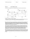
The azim_fast_deadband_msec and azim_slow_deadband_msec items are used for the anti-reversal
system. To understand the purpose of these parameters, it is necessary to consider how position counts
are accumulated. The feedback from the azimuth and elevation position sensors is pulses. When a
pulse is received, the controller checks to see which way the antenna was last commanded to move. If
the antenna is moving, or last moved, east (down), the azimuth (elevation) position count is decremented.
If the antenna is moving, or last moved, west (up) the azimuth (elevation) position count is incremented.
In MANUAL mode, the user can jog the antenna. If the UP arrow key is depressed, the antenna will
move up. If the user suddenly depresses the DOWN arrow key and the antenna drive signals were
instantaneously reversed, the antenna continues to move up for some small period of time, then the
antenna reverses direction and starts to move down. This can cause position count errors. When the
antenna drive signals are configured for down movement but the antenna is still moving up, pulses which