


RC3000 Antenna Controller Chapter 1 Introduction
6
- performs communications between the microcontroller and the three (GPS, compass, remote control)
serial channels
- performs analog to digital conversion of drive position and signal strength inputs
- performs automatic antenna movement algorithms (locate, stow, recall, track, etc)
FEATURE BOARD. The feature board contains circuitry to implement many of the optional features of
the RC3000. The feature board provides the following major functions:
- signal drivers for PC remote control and navigation sensor serial communication
- circuitry for multiplexing signal strength indications from 1 of 3 sources
- circuitry for conditioning pulse based position feedback signals
- power transformation to supply required voltages to other modules
RF AUTOPEAK MODULE. This module accepts the output of an LNB (950-1450MHZ, -50 to –5dBm)
and generates a signal indicative of power across the band. This signal may be used for autopeak
operations.
ANALOG BOARD. The analog board contains circuitry to control the antenna motors and condition
antenna feedback signals. The analog board provides the following major functions:
- generation of azimuth and polarization limit indications based on sensed potentiometer feedback
- conditioning of elevation inclinometer input
- conditioning of azimuth stow and elevation up/down/stow limit switch inputs
- activation of relays (based on digital board control) to direct motor drive signals from the DC motor
control module.
DC MOTOR CONTROL MODULE. The solid state DC motor speed and reversing control module
contains circuitry for antenna motor regulation. This module provides:
- acceleration adjustment for smooth motor acceleration
- deceleration adjustment for ramp down time when motor speed lowered
- anti-plug instant reverse, solid state dynamic braking
- current limiting circuitry to protect the motor against overloads and demagnetization and to
limit inrush current during startup
- IR compensation to improve load regulation
POWER ENTRY MODULE. The power entry module allows the RC3000 to be configured for 115 or 230
VAC operation.
POWER TRANSFORMER. The power supply module transforms AC input voltage to a regulated DC
voltage for use by the digital and drive boards.
RESOLVER BOARD. To support mounts that use resolvers for position feedback, an optional resolver to
digital conversion board may be added to the baseline RC3000 hardware.
NOTE: Second Generation RC3000's (serial number > 2000) will have the circuitry of the analog board
and the feature board combined. Section 5.0 will contain the appropriate schematics for a particular
controller.
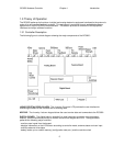
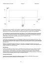
1.3.2 System Interface Requirements
The RC3000 is designed to interface with many different mobile antenna mounts. This manual attempts
to describe installation and operation in a manner applicable to most mounts.
The typical interfaces required for the RC3000 to perform all its automatic functions are described in
section 2.2 (Electrical Connections). Known differences to these interfaces and how they are
accommodated for a particular mount are described in appendix B (Mount Specific Data).