


RC3000 Antenna Controller Chapter 3 Detailed Operation
102
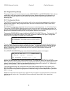
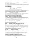
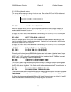
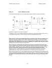
3.3.1.2.3 Azimuth Calibration
REF_V:2.50 FG: 0.0 CONFIG-AZIM
CCW:180 CW:180 SF:65.62
DISP:1
SET REFERENCE VOLTAGE <2.00 – 3.00>
REF_V: SET REFERENCE VOLTAGE <1.00 - 4.00>
The azim_zero_voltage defines the voltage present when the azimuth axis is in its center of motion. See
the azimuth zero voltage installation section 2.3.3.
CCW: SET CCW LIMIT <0 TO 360 DEGREES>
CW: SET CW LIMIT <0 TO 360 DEGREES>
These items specify the antenna's azimuth range of travel relative to the antenna’s center azimuth (0.0)
position. These positions are used to trigger the display of the Reposition Truck message. When the
RC3000 calculates an antenna pointing solution in LOCATE mode, it checks these values to see if the
dish can be physically moved to that position. Thus the Reposition Truck message is displayed when the
antenna is incapable of moving to the azimuth position required to intercept the desired satellite. These
values are also used by autopeak algorithms to limit the area the autopeak movements will search.
Note that these values are not used to actually limit the motion of the antenna. The antenna's azimuth
limits are set using potentiometers inside the controller (see 2.3.1.4 - Azimuth and Polarization Electrical
Limits). The CW Range should be set to the azimuth position which is displayed when the antenna is at
the CW limit. In a similar manner, the CCW Range should be set to the azimuth position which
corresponds to the controller's azimuth counter-clockwise limit. Note that the values are entered as a
positive value, the controller will adjust the sign of the entered quantity internally.
FG: FLUXGATE OFFSET <-180.0/+180.0 DEGREES>
The azim_cal_offset item specifies the number of degrees to offset the heading reading with respect to
the heading of the centerline of the azimuth axis. The default value for this reading is 0. A value other
than 0 may need to be entered to correct for some mechanical misalignment in the system (see Azimuth
and Elevation Alignment 2.5.2).
This value will also need to be set if there is an intentional difference between the alignment of the
compass and the centerline of azimuth movement.
SF: SCALE FACTOR <1.00 – 90.00 deg/volt>
This value specifies the azimuth scale factor applicable to the potentiometer-based azimuth feedback.
NOTE: The default value for this item will typically be correct.
DISP: INITIAL AZIM DISPLAY<1-ANT 3-MAG 4-TRUE>
This value allows the user to select what format (antenna angle, magnetic heading or true heading) the
azimuth position is initially displayed in the MANUAL and LOCATE modes. Traditionally, the antenna
angle derived from the mount position sensor is the format displayed by the RC3000.