


RC3000 Antenna Controller Chapter 2 Installation
51
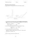
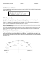
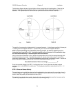
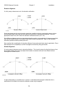
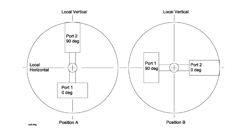
The following diagram shows a typical situation of two waveguides that rotate together. Note that the
diagram should be considered as if the observer is behind the reflector looking towards the arc of
satellites. This representation is relevant for both prime focus and dual reflector antennas.
The polarity of a waveguide is determined by its narrow dimension. In the diagram, position A shows port
1 as being at the 0.0 degree orientation. In position B, port 2 is at the 0.0 degree orientation.
NOTE: before establishing the polarization reference position, the antenna platform must be
leveled so there is no pitch or roll. Any platform pitch and/or roll present in this calibration step
will later cause inaccuracy in automatic polarization movements.
Using an accurate inclinometer or level, position the polarization axis so that the waveguides align with
the local vertical and horizontal. Typically this position will also be close to the center or travel of the
polarization potentiometer. If not, adjust the polarization potentiometer to achieve this value. Secure the
pot and record the voltage read from the VOLTAGES maintenance screen (3.3.2.1).
Recorded Polarization Reference Voltage ______________ V.
Enter the recorded voltage in the REF_V configuration item. To verify that data has been entered
correctly, return to the MANUAL mode screen. The displayed polarization angle should be 0.0 +/- 0.1
degrees.
STEP 3. Drive and Sensor Polarity.
The polarization motor should be wired so that the polarization axis rotates per the convention shown in
the above diagram. Jog the polarization from the MANUAL mode to confirm the correct rotation. If not
correct, check the polarity of the motor drive lines (2.2.2).
The polarization potentiometer must be wired so that the sensed polarization position increases as the
Pol CW key is depressed. If not correct, check the sensor wiring (2.2.3).