


RC3000 Antenna Controller Chapter 2 Installation
50
2.3.4 Polarization Calibration
The following steps will require values to be entered in the POLARIZATION CALIBRATION configuration
screen (see 3.3.1.2.4).
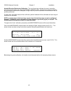
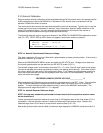
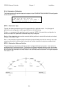
REF_V:2.50 OFF: 0.0 CONFIG-POL
CCW: 90.0 CW: 90.0 SF:41.67
TYPE:2 REF:1 H: -45.0 V: 45.0 AUTO: 1
SET REFERENCE VOLTAGE <2.00 – 3.00>
STEP 1. Polarization Type.
Typically the default polarization type will be appropriate for a particular mount. If not, the type of
polarization axis configuration must be specified as one of the following:
Circular – no movement of the polarization axis is required. NOTE: if the polarization configuration is
circular, the rest of the polarization calibration steps may be skipped.
Single – If the polarization axis must be moved to distinct positions to orient with horizontal and vertical,
the type is considered single.
Dual – If the polarization system contains two feeds (or sets of feeds) such that the axis only has to be
moved to one position to achieve both horizontal and vertical orientation, the type is considered dual.
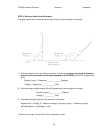
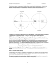
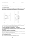
STEP 2. Polarization Reference Position.
The polarization axis should be positioned so that it is aligned with the local vertical. Local vertical is
considered the 0.0 polarization angle. Clockwise and counterclockwise is defined as seen by a person
looking from behind the antenna out towards the arc of satellites. In MANUAL mode, when the Pol CW
key is pushed the polarization axis must rotate in the clockwise direction as shown in the figure repeated
from section 1.3.8.