


RC3000 Antenna Controller Chapter 3 Detailed Operation
99
3.3.1.2 INSTALLATION ACCESS ITEMS
This set of configuration groups allows the user to modify parameters that are most typically changed for
a particular installation.
3.3.1.2.1 System Definition
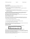
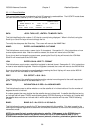
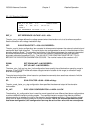
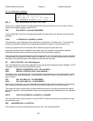
GPS: 1 CONFIG-SYSTEM
COMPASS: 1 SN:1234 WAVEGUIDE:0
MODE: 2 ANT_SIZE: 120
<1>GPS PRESENT <0>NOT PRESENT
The CONFIG-SYSTEM screen allows the user to indicate the existence of optional equipment. Indicating
that the item is not present will keep the controller from waiting for a valid response from the item in
various modes. For example, if the GPS receiver is not present, the RC3000 will simply report “NO GPS
PRESENT” vs. waiting for a period of time to decide that it is not receiving data from the GPS.
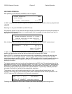
GPS : <1>GPS PRESENT <0>NOT PRESENT
This item specifies whether or not the optional GPS receiver is present. If specified as not present (0),
the “NO GPS PRESENT” message will be displayed in various RC3000 screens.
If the GPS option was not purchased, this field will always remain at 0.
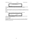
COMPASS: <0>NONE <1>TRUCK MOUNT <2>ANTENNA MOUNT
This item specifies whether or not the optional fluxgate compass is present and how the compass is
mounted if it is present. If the compass is specified as “antenna mounted”, the RC3000 will require that
the dish be moved to the DEPLOY position to obtain magnetic heading information.
If the compass option was not purchased, this field will always remain at 0.
SN: SERIAL NUMBER<1-9999> (0=NOT ENTERED)
The serial number of the controller may be entered in this field for easy reference later. The value of this
field does not affect of the controller's functions.
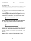
MODE: INITIAL MODE <1-LOCATE 2-MENU 3-MANUAL 4-VSAT 5-POS>
This item specifies to which of the modes listed the RC3000 will go to upon power up.
Selections 1, 2, 3 or 5 will direct the RC3000 to go to LOCATE, MENU, MANUAL or POSITION mode
upon power up. For example, if the controller does not have the GPS and compass options, the user
may want to power on to the POSITION mode.
Selection 4 puts the controller in “VSAT” mode described in section 3.2.2.11. This section should be
thoroughly reviewed prior to placing the controller into “VSAT” mode.
ANT_SIZE: ANTENNA SIZE <1-9999 CM>
This item specifies the size of the reflector in centimeters. For example, a 5.9 ft. diameter reflector (1.8
m.) would require a value of 180 (cm.) be specified.
The antenna_size_cm is used by inclined orbit tracking algorithms to characterize the antenna’s
beamwidth thus affecting timing of various tracking movements. The value is also used by autopeak
algorithms to determine the size of autopeak step movements.
WAVEGUIDE: WAVEGUIDE SWITCH <1>PRESENT <0>NOT PRESENT
This item specifies whether or not the optional waveguide switch control module is present.