


RC3000 Antenna Controller Chapter 2 Installation
35
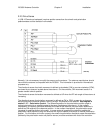
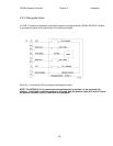
2.2.10 Pulse Sensors
NOTE: Pulse sensors are typically only installed on some mounts in order to mechanize the
optional inclined orbit tracking feature. This section may be skipped if pulse sensors are not
present.
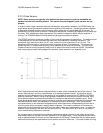
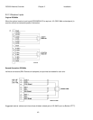
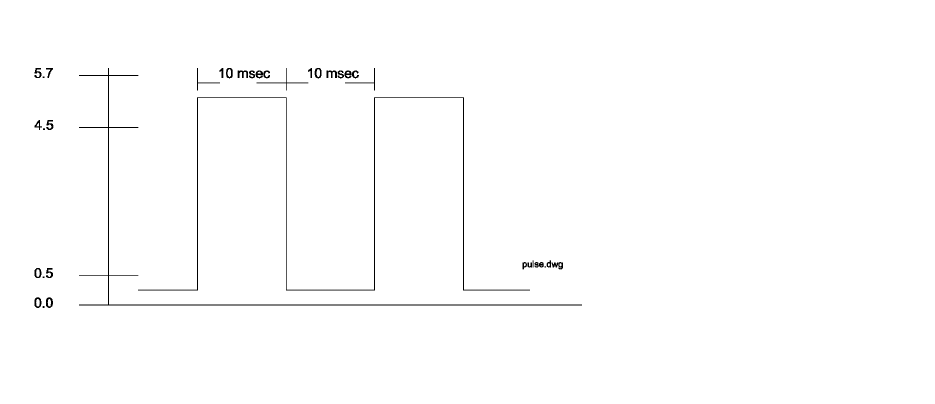
In order to obtain higher resolution azimuth and elevation axis position feedback, the RC3000 may use
single phase pulse type sensors to determine the position of the antenna. A pulse type sensor produces
a rectangular shaped waveform as the antenna moves about the axis associated with the sensor. A
quadrature pulse type sensor produces 2 rectangular waveforms, one being 90 degrees out of phase with
the other. With a quadrature type pulse sensor it is possible to determine which way the antenna is
moving. The RC3000 software currently does not yet support quadrature sensors.
The RC3000 controller counts the number of rising and falling edges of the waveform. The position count
is decremented for counter-clockwise movement and incremented for clockwise movement. The
waveform's high level should be 4.5 to 5.7 volts, and the low level should be 0.0 to 0.5 volts. The
waveform's minimum high or low pulse duration should be at least 10 milliseconds. This means that
pulses less than 10 milliseconds long may not be detected by the antenna controller. The maximum
number of counts from the antenna's east limit to its west limit should be less than 65535. Remember,
each rising edge and each falling edge of the sensor's output waveform is a separate count.
Many large antennas use a sensor attached directly to each of the fundamental axis of the antenna. The
sensor used may be a synchro, potentiometer, or a quadrature pulse encoder. A pulse type sensor
attached to the fundamental axis of the antenna is not suitable for use with the RC1000A or RC2000A
antenna controllers. When a rising or falling edge is detected on the antenna controller's sensor input,
the antenna controller must determine whether to increment or decrement the position count. Since
single phase pulse sensors are used, the antenna controller must determine which way the antenna was
last commanded to move, and decrement or increment the count accordingly. With a pulse sensor
connected directly to the antenna's fundamental axis, when the antenna vibrates back and forth due to
wind, the pulse sensor produces a steady stream of pulses. The antenna controller will increment or
decrement the count depending on which way the antenna was last commanded to move. In reality the
antenna is just vibrating in the wind and not really moving. The result of this is an error in the position
count maintained by the antenna controller.
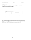
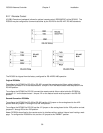
On a large antenna, the solution to the sensor dilemma is to place a sensor on the output of the motor.
Most motors attach to the gear reduction systems via a C56 type flange. There are pulse sensors which
may be placed between the motor and the transmission at this flange. Remember that any pulse sensor
used must conform to the requirements of the antenna controller, which are: 1) the total number of rising