


RC3000 Antenna Controller Chapter 3 Detailed Operation
105
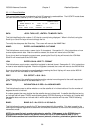
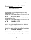
3.3.1.2.5 Signal Strength Factors
This screen defines how signal strength inputs are used. See sections 2.2.5 and 2.4.3 for references to
the use of signal strength inputs.
RF LOCK:0 TIME:0.1 CONFIG-SIG
SS1 LOCK:0 TIME:0.1 TH:100 POL:0
SS2 LOCK:0 TIME:0.1 TH:100 POL:0
<0>NEGATIVE <1>POSITIVE AGC INPUT SENSE
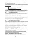
RF LOCK: <0-NONE 1-1HI 2-1LO 3-2HI 4-2LO>
When the autopeak source is the RF input, this item defines whether a discrete signal lock input is
required to indicate a satellite has been found. The signal lock input may help in distinguishing the
correct satellite while doing a LOCATE.
If a signal lock input is used, it may be defined as either having a HI (>3.5 VDC) or LO (< 0.8 VDC) level
that indicates lock.
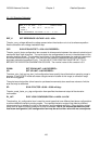
SS1 LOCK: LOCK TYPE <0>NONE <1>HI <2>LO
SS2 LOCK: LOCK TYPE <0>NONE <1>HI <2>LO
When the autopeak source is the SS1 or SS2 input, these items define whether a discrete signal lock
input is required to indicate a satellite has been found. The signal lock input may help in distinguishing
the correct satellite while doing a LOCATE.
If a signal lock input is used, it may be defined as either having a HI (>3.5 VDC) or LO (< 0.8 VDC) level
that indicates lock.
RF TIME: RF DELAY TIME <0.1 – 9.9> SECONDS
SS1 TIME: SS1 DELAY TIME <0.1 – 9.9> SECONDS
SS2 TIME: SS1 DELAY TIME <0.1 – 9.9> SECONDS
These items define how long the RC3000 will wait after each step before sampling signal strength.
Increasing this value may be required to allow equipment such as a modem to generate an AGC output.
NOTE: if a RF_LOCK value of 0 (no signal lock conditioning) is selected, the RF_TIME item is ignored
and a smooth (non-stepping) scan will be implemented.
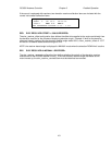
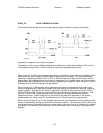
SS1 POL: <0>NEGATIVE <1>POSITIVE INPUT SENSE
SS2 POL: <0>NEGATIVE <1>POSITIVE INPUT SENSE
The SS1/SS2 polarity flags tell the controller what the sense is on the signal strength input voltage used
for tracking and autopeak operations. A positive sense is defined as one that increases in magnitude as
the RF signal strength increases. If the signal strength voltage decreases as the RF signal increases, its
polarity is considered negative.
SS1 TH: SS1 MINIMUM SIGNAL THRESHOLD <0-999>
SS2 TH: SS2 MINIMUM SIGNAL THRESHOLD <0-999>
These threshold items define what the minimum signal strength indication for each channel is required for
the tracking system to “recognize” that a satellite is present. NOTE: these items are only applicable to
TRACK mode.
If different bands are received that exhibit different “off satellite” signal strengths, the highest “off satellite”
value should be used to avoid the possibility of recognizing noise as a satellite.