


RC3000 Antenna Controller Chapter 3 Detailed Operation
123
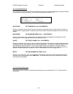
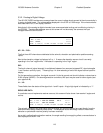
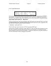
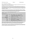
3.3.2.5 Limits Maintenance
AZIM CW:0 CCW:1 STOW:0 (0-OFF) LIMITS
ELEV UP:1 DN:1 STOW:1 (1- ON) ACTIVE
POL CW:0 CCW:1 STOW:*
<BKSP>MAKE LIMITS INACTIVE <MODE>EXIT
The limits maintenance screen shows the current state of each limit switch as sensed by the RC3000’s
microcontroller. The state of each limit is shown as 0 if off or 1 if on. An * is displayed if the particular
limit switch is not relevant for the particular mount (there is no POL STOW switch in the above example).
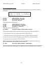
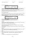
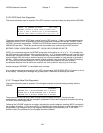
<BKSP>MAKE LIMITS INACTIVE <MODE>EXIT
From this screen the user may inactivate software logic that prevents axis movement due to a limit switch
by pressing the BKSP switch. Note that inactivating limits should be done with caution. Whenever limits
are “INACTIVE” the alarm system will flash the following:
** WARNING – LIMITS INACTIVE **
The limit switch logic may be returned to “ACTIVE” by pressing BKSP again.
Note that even if software limit sensing is made “INACTIVE”, there are cases where movement of an axis
may still be inhibited by hardware logic (sensing the state of limit switches) on the analog drive board.
Good knowledge of how the various limit switches in a system are mechanized is required to determine if
the limits inactive state will help in debugging any problems.