


RC3000 Antenna Controller Chapter 3 Detailed Operation
119
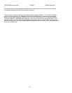
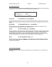
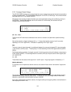
3.3.2.1 Analog to Digital Voltage
The AD VOLTAGES maintenance screen shows the current voltage levels sensed at the microcontroller’s
4 analog to digital inputs. The voltage will be displayed in the 0.001 to 5.000 range. If the microcontroller
sees less than 0.001, it will display “UNDER”.
Note that all of the analog to digital channels have some associated scaling and conditioning circuitry in
the RC3000. Therefore the voltages seen at this screen will not be exactly the same as the input
voltages external to the RC3000.
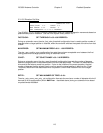
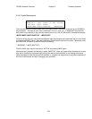
AZ: 1.114 AD VOLTAGES
EL: 1.143 1 L1:1
POL: UNDER L2:0
SIG: 3.756(1) <1>RF <2>SS1 <3>SS2 <4>AUX
AZ: / EL: / POL:
The first three A/D channels are dedicated to the azimuth, elevation and polarization position sensing
inputs.
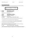
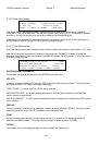
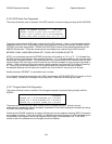
Next to the elevation voltage is displayed a 0 or 1. 0 means the elevation sensor circuit is currently
operating in the “low” region while 1 indicates it is operating in the “high” region.
SIG:
The fourth channel (signal strength) is multiplexed between four sources (autopeak RF, signal strengths
1 and 2 and an auxiliary input). Pressing keys 1-4 allow selecting of one of the signal source inputs for
display.
On first generation controllers, the signal source # 4 is tied to ground and should indicate a value close to
0.000 (maybe UNDER). On second generation controllers, this input may be used for other signals (see
your appendix B).
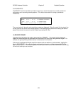
L1: / L2:
These fields show the status of the signal lock 1 and 2 inputs. A logic high signal is indicated by a “1”.
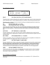
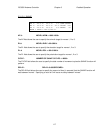
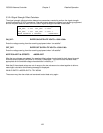
RESOLVER DATA
If a particular mount implements resolver sensors, this screen will also shows “raw resolver” angles and
counts.
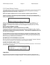
AZ: 1.114 181.30 33004 AD VOLTAGES
EL: 1.143 1 122.30 22264 22.3 L1:1
POL:2.237 181.30 33044 L2:0
SIG: 3.756(1) <1>RF <2>SS1 <3>SS2 <4>GND
The azimuth, elevation and polarization resolver angles and counts displayed are read directly from the
resolvers without being biased by offset terms. The displayed values will though reflect if the azimuth,
elevation or polarization resolver polarity has been reversed.
As an aid in calibrating the elevation resolver, the angle resulting from applying offset a reverse factors is
also displayed on the EL: line.