


RC3000 Antenna Controller Chapter 2 Installation
42
Azimuth/Elevation/Polarization Calibration. The next three steps calibrate the mount’s elevation,
azimuth and polarization axes. Place the RC3000 in MANUAL mode. Values for the azimuth, elevation
and polarization axes should be displayed, though they may not be reasonable since calibration has not
yet been performed.
For each axis, limit switch status will be confirmed, position feedback will be calibrated and total range of
movement will be tested.
NOTE: be careful when initially moving a mount since limit switches may not yet be configured
correctly. In MANUAL mode, movement will stop whenever a particular jog key is released. The
RC3000 may also always be turned off to stop movement.
Throughout the 3 axis’ calibration procedures, two MAINTENANCE screens will be used extensively.
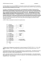
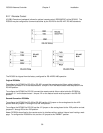
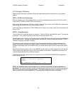
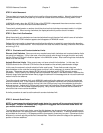
One of the MAINTENANCE screens used is the Analog to Digital Voltage screen (see 3.3.2.1). This
screen shows raw data coming from antenna position sensors (potentiometers and resolvers).
AZ: 1.114 181.30 33004 AD VOLTAGES
EL: 1.143 1 122.30 22264 22.3 L1:1
POL:2.237 181.30 33044 L2:1
SIG: 3.756(1) <1>RF <2>SS1 <3>SS2 <4>GND
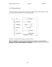
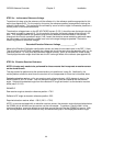
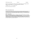
Another MAINTENANCE screen that will be used is the Limits Maintenance screen ( see 3.3.2.5). This
screen shows the current sensed state of limit switches for all three axes.
AZIM CW:0 CCW:1 STOW:0 (0-OFF) LIMITS
ELEV UP:1 DN:1 STOW:1 (1- ON) ACTIVE
POL CW:0 CCW:1 STOW:0
<BKSP>MAKE LIMITS INACTIVE <MODE>EXIT
Before beginning axes calibration, the installer should become familiar with accessing these screens.