


RC3000 Antenna Controller Chapter 2 Installation
55
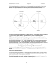
2.4.2 Azimuth and Elevation Alignment
This step attempts to discover and compensate for offsets in azimuth and elevation position sensing.
Offsets may be introduced due to mechanical tolerances, slight inaccuracies in installation, etc. For
example, the compass may not be exactly aligned with the azimuth reference position or the elevation
inclinometer was not rigged perfectly.
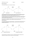
The alignment procedure relies on the fact that is it possible to determine how the dish is pointing based
on the actual antenna angles required to intercept a satellite (at a known longitude) when the vehicle's
latitude and longitude are known.
NOTE: before performing this step, the elevation offset value should be set to 0.0.
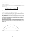
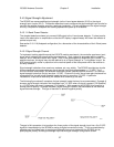
To determine the azimuth and elevation offsets, the vehicle is positioned at a number of different
headings. At a given heading, the operator allows the controller to calculate the azimuth and elevation
positions required to LOCATE a pair of satellites. These calculated positions are recorded. The operator
then manually peaks the antenna to align the antenna with the satellites perfectly. The azimuth and
elevation angles where the satellites are actually found are recorded. The difference between the
calculated (or target) positions and the positions where the satellites were actually found are calculated.
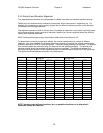
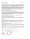
The results should be tabulated as shown in the table below.
AZIMUTH ELEVATION
HDG. SAT CALC’D ACTUAL DIFF. CALC’D ACTUAL DIFF.
1 1
2
2 1
2
3 1
2
4 1
2
5 1
2
6 1
2
7 1
2
8 1
2
TOTAL
AVG.
NOTE: As many tests (different locations, etc.) as possible should be run to determine if
consistent offsets are observed.