


RC3000 Antenna Controller Chapter 2 Installation
24
2.2 Electrical Connections
This section provides cabling requirements for interfacing to the RC3000. Note that cables should be
made long enough to allow the unit to be open while still connected to the system.
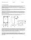
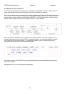
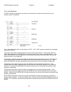
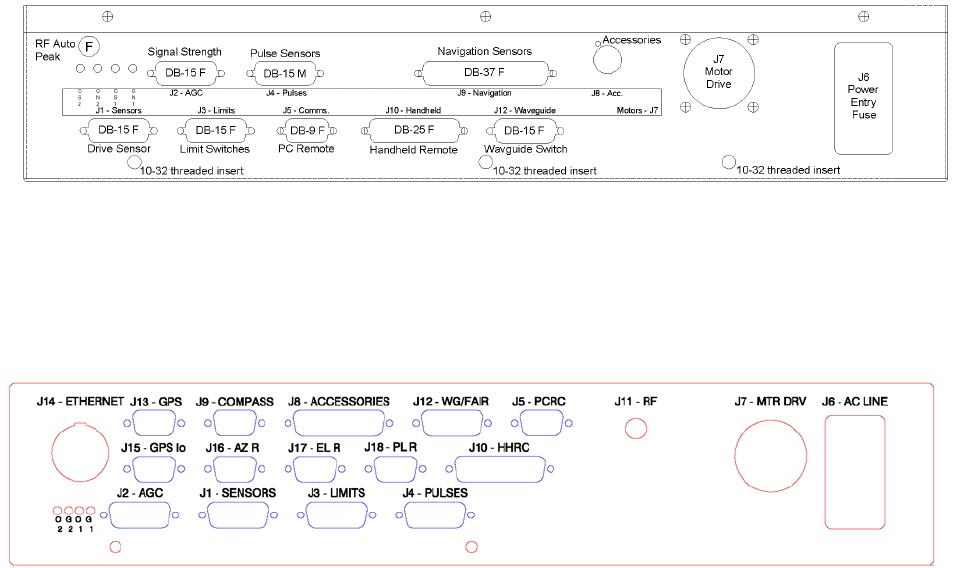
The following sections supply a schedule of connection requirements. Note that the pinout requirements
for J1, J3, J6, J7 and J10 are the same as required for RC8097 installations and therefore should not
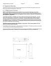
require rework of those cables for retrofitting to the RC3000. The following diagram shows the typical
location of the backpanel connectors on original (serial # < 2000) controllers.
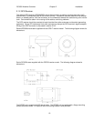
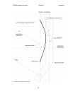
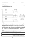
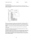
Second Generation RC3000s (serial # > 2000) have a slightly different connector arrangement. For
example, rather than having a single DB-37 for navigation sensors, the second generation controllers
have individual DB-9s for each sensor. Any differences between original and second generation
connectors will be described in the following paragraphs.
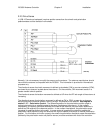
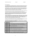
Also, some versions of the RC3000 have customized backpanels to accommodate existing antenna
connector schemes.
See appendix B for your exact backpanel configuration.