


RC3000 Antenna Controller Chapter 2 Installation
28
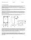
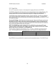
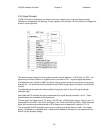
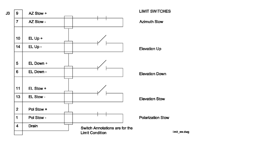
2.2.4 Limit Switches
J3 (DB-15 Female on backpanel) connects to the azimuth stow, elevation stow, elevation up and
elevation down limit switches.
The + side of each limit switch circuit supplies 12 VDC. This 12 VDC supply is protected by a resettable
fuse rated at 250 mA.
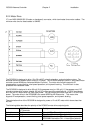
The azimuth stow switch must be closed when at the azimuth stow position. If the azimuth stow limit
switch cable is severed, the RC3000 will think that the azimuth axis is not at the stowed position. Logic
within the RC3000 will not allow elevation to move below the elevation down limit switch if an azimuth
stowed condition is not recognized.
The elevation up switch must be open when the elevation axis has reached the up limit. If the elevation
up limit switch cable is severed, the RC3000 will think that the elevation axis is at the up limit. Logic
within the RC3000 will not allow the elevation axis to move up if an up limit condition is recognized.
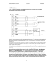
The elevation down switch must open when the elevation axis has reached the down limit. If the
elevation down limit switch cable is severed, the RC3000 will think that the elevation axis is below the
down limit. Logic within the RC3000 will not allow the azimuth axis to move when the elevation down
condition is recognized.
The elevation stow switch must open when the elevation axis has reached the stow position. If the
elevation stow limit switch cable is severed, the RC3000 will think that the elevation axis is at the stow
position. Logic within the RC3000 will not allow the elevation axis to move down when the elevation stow
condition is recognized.
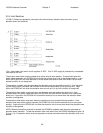
NOTE: When the elevation stow limit is sensed, the RC3000’s hardware also internally generates an
elevation down indication. To test the elevation down limit switch from the RC3000’s backpanel (pins 5 &
6), pins 11 & 13 (elevation stow) must be jumpered to simulate a situation where the elevation axis is not
stowed.