


RC3000 Antenna Controller Chapter 2 Installation
31
2.2.7 Accessories
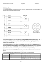
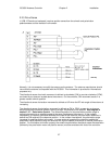
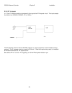
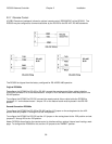
J8 (9 pin DB-Receptacle) is an accessory connector. It contains pins that support the following functions
of the RC3000: High-power-amplifier (HPA) disable, system alarm contact closure output, 1 pulse-per-
second output (optional depending on GPS in-use), and a circuit that can allow for instant access to the
GPS position solution. On some units, two of the pins may be diverted to power auxiliary equipment.
The HPA disable is in a form-C contact arrangement with a normally-open, normally-closed and common
contacts. While the antenna is below the down elevation limit or while the antenna is performing any
large-scale auto-moves, such as deploy, locate, or stow, the normally-closed and common pins will be
connected. After the auto-move is complete, the connection will be released.
The Alarm output contact closure consists of a normally closed and a common contact. In the advent of a
RC3000 mains power failure, the contact will close allowing an audible alarm or lamp to be lit.
The instant GPS solution feature is realized by powering the GPS receiver(s) during transit to the shoot
location and for a roughly 30 minute period after the vehicle ignition is turned off. Without this feature,
GPS solution lock-up time will range from 2 to 4 minutes after RC3000 power up. The exact time
depends on how long it has been since the receiver last had a solution and how far the receiver has
moved from its last location.
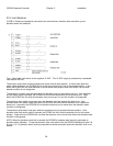
The Instant GPS feature requires a connection to the vehicle +12V battery system (+12V to +14V on all of
the time), a connection to the +12V vehicle accessory voltage (+12V on while the vehicle ignition system
is on), and a connection to the vehicle chassis ground. While the vehicle ignition system is on and for 30
minutes after the ignition is shut off, power is routed to ports 1, 3, and 4 of the navigation sensor
connector, J9. This feature must be enabled on the RC3000 feature board by installing diodes D31 and
D29. The GPS receiver will typically draw less than 200 mA. at 12VDC.
On certain units, when requested at the time of order, an unregulated power supply voltage can be made
available on pins 2 and 8 of this connector at the expense of the instant GPS feature.
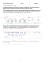
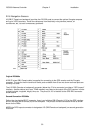
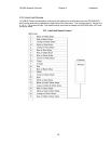
Earlier RC3000 models mechanized J8 via a round Amphenol 126 series connector. Second Generation
controllers put the HPA and alarm relays on a DB-25 (Female on backpanel) connector. The following
table shows the pin connections for all connector types.
DB-
9
AMP
126
DB-
25
DESCRIPTION
1 A 1 HPA Disable, normally-open, 3A @ 30VDC max or 3A @ 250VAC max
2 B +12 - +14V Vehicle Battery input (OR +Vunreg. for auxiliary output models, 2A
max)
3 C Ground, Vehicle chassis ground input
4 D 15 HPA Disable, common, 3A @ 30VDC max or 3A @ 250VAC max
5 E 3 HPA Disable, normally-closed, 3A @ 30VDC max or 3A @ 250VAC max
6 F 16 Alarm common, 3A @ 30VDC max or 3A @ 250VAC max
7 H 4 Alarm normally-closed, 3A @ 30VDC max or 3A @ 250VAC max
8 J +12 to +14V Vehicle accessory input (Vunreg. Return for auxiliary output models)
9 K 1PPS output, TTL compatible (only available GPS model 36 receiver)
The other pins on the DB-25 connector are available for custom interface requirements. See Appendix B.