


RC3000 Antenna Controller Chapter 2 Installation
49
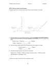
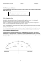
Example: at +90 degree reference position the azimuth voltage is 3.86. At the –90 degree reference
position the azimuth voltage is 1.14. The azimuth scale factor is calculated as:
180 degrees / (3.86 –1.14) = 66.16 degrees / volt.
66.16 would be entered as the scale factor.
STEP 6. Azimuth Software Limits.
The CCW and CW configuration item values should be set to reflect the physical limits of azimuth travel.
Note that these limits don’t physically limit azimuth travel but are used by software to determine if a
calculated pointing solution is outside of the mount’s range of movement. If a calculated pointing solution
is beyond these limits the message “AZIM RANGE ERROR” will be displayed in the LOCATE screen.
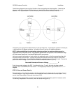
STEP 7. Fluxgate Offset.
NOTE: this item defines the difference in orientation (in the azimuth axis) between the fluxgate
compass (2.1.3) and the azimuth reference (displayed 0.0) position. This value should initially be set
to the apparent difference between the compass’ and azimuth axis orientations. For example, if the
compass is placed on the vehicle facing forward and the dish actually faces backward, an azimuth offset
of 180 would be entered. It is recommended that the compass be placed facing in the same direction as
the azimuth centerline thus requiring an offset of 0.0.