


RC3000 Antenna Controller Chapter 3 Detailed Operation
79
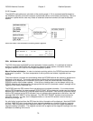
3.2.2.3.2 LOCATE Automatic Movement
Before automatic movement to the calculated position is initiated, the RC3000 requests that a polarization
position be selected. This is so the polarization mechanism will be in the correct position to be able to
detect received signal strength.
Note: this selection is not requested if the polarization configuration is defined as “circular” or if the
polarization automove is disabled via the polarization configuration screen (3.3.1.2.4). In this case the
RC3000 will only request that the user press the BKSP key to confirm that the automatic LOCATE
movement is to proceed.
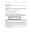
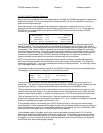
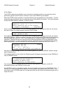
H-HORIZONTAL: 85.4 LOCATE
V- VERTICAL: -4.6 SAT:GALAXY 7
8- NEUTREAL: 40.4 <MODE>MENU
<H/V/8> SELECT POLARIZATION <BKSP>NONE
The RC3000 calculates the vertical polarization position as a function of mount latitude/longitude and
satellite longitude. The horizontal position is calculated as 90 degrees from the vertical in the direction
(Clockwise/Counter-Clockwise) that will maintain the horizontal position within the polarization axis’ range
of movement. The “neutral” position represents the polarization angle halfway between the calculated
vertical and horizontal values. The neutral position may be appropriate if the autopeak function is using
the L-Band detector (RF) input for signal strength observation. If the user does not want a polarization
movement to be performed for this LOCATE, pressing the BKSP key will initiate the elevation and
azimuth automatic movements but a polarization movement will not be performed.
NOTE: If the polarization calculation determines that the correct orientation is outside the polarization
axis’ limits, the target position will be achieved by moving the position by 90 degrees. This situation is
annotated by placing an “*” next to the calculated horizontal and vertical positions. The user may need to
“flip” a waveguide switch in this case.
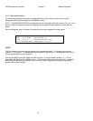
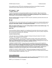
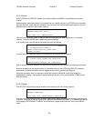
Immediately following the polarization selection, the RC3000 will begin moving to the calculated position.
The progress of the movement is displayed on the following screen.
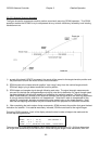
AZIM: 0.0 ( -5.9) LOCATE
ELEV: -61.7 ( 44.8) SAT:GALAXY 7
POL: 0.0 ( -45.0)
MOVING TO (TARGETS) <STOP>HALT MOTION
The current angular values for az/el/pol are displayed along with the target position for each axis in
parenthesis. The label for the current axis being moved will flash. Movement may be halted at any time
by pressing the Stop key. Halting movement will return the controller to the MANUAL mode.
The first automatic movement will be in the elevation axis to ensure that the mount is brought out of the
elevation stow and down regions. The next movement will be in the polarization axis to ready the feed
system to detect signal strength. If enabled, tilt compensation (3.2.2.3.6) movements will be performed.
The final movement will be in the azimuth axis. How this movement is accomplished depends on
whether the autopeak system (see Autopeak Configuraion 3.3.1.2.6) is enabled and whether the selected
satellite is described as having an inclined orbit or not.
If the autopeak system is not enabled, the LOCATE mode will finish by moving to the nominal target
azimuth position. A final movement to the target elevation will also be performed to account for change in
mount elevation due to vehicle tilt. Following this movement, the controller will return to MANUAL mode
where the user should peak up and confirm the identity of the satellite.
If the autopeak system is enabled, an azimuth scanning autopeak movement (see 3.2.2.3.3) will be
performed if the selected satellite does not have an inclined orbit. If the satellite does have an inclined
orbit a spiral search movement (see 3.2.2.3.4) will be performed. For both autopeak movements to be
successful, the user is required to have the receiving equipment (prior to the movement) configured for
the RC3000 to be able to detect signal strength.