


RC3000 Antenna Controller Chapter 3 Detailed Operation
69
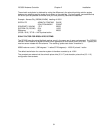
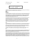
3.2.1 Manual Mode
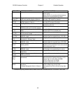
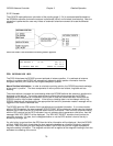
AZIM: 0.0 STOW SS1: 50 MANUAL
ELEV: -42.5 DOWN SAT:TELSTAR 402
POL: 30.0 V SPD:FAST CST
<0-9>JOG ANTENNA <MODE>MENU 14:25:47
In MANUAL mode, the user may jog the antenna in all three axes. A momentary push of the Mode key
will move the controller from the MANUAL mode to the MENU mode.
AZIM:
MAG:/mag:
TRUE:/true
The azimuth field shows a current position value of the azimuth axis. It also shows the status of azimuth
limits (STOW, CCW, CW). The azimuth axis may be moved by pressing the Az CCW or Az CW keys.
The value displayed may be changed by the Scroll Up/Angle CT key. The display will rotate between
showing antenna angle, antenna pulse count, magnetic heading and true heading values. When first
entering MANUAL mode, the field will always be initialized in the display mode selected by the
initial_azimuth_display configuration item (3.3.1.2.3).
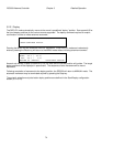
The magnetic and true heading values are derived by taking the current heading estimate of the mount
(see the LOCATE function) and adding the antenna angle. If there is currently no mount heading
estimate, the field will display "-------". If the current heading estimate has not been "fixed" (either
manually or automatically by the DVB receiver function), the field will be annunciated by small letters
(mag: or true:) to indicate that the heading value may be inaccurate due to compass error. If the
RC3000's heading estimate has been "fixed", the field will be annunciated in capital letters (MAG: or
TRUE:) to indicate confidence that the value represents an accurate magnetic or true heading.
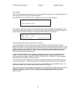
ELEV:
The ELEV field shows a current position value of the elevation axis. It also shows the status of elevation
limits (STOW, DOWN, UP). The elevation axis may be moved by pressing the El Up or El DN keys.
NOTE: when the azimuth field shows a pulse count value (due to pressing of the Scroll Up/Angle CT
key), the ELEV field will also show the current elevation pulse count. During the other three choices of
azimuth display, the field will show the elevation angle derived from the inclinometer.
Following a LOCATE operation, the azimuth and elevation limit fields will display the target angles in
parenthesis. If a limit condition is active, the limit display will overwrite the target values.
POL:
This field shows the current angular value of the polarization axis along with its limits (CCW, CW). This
field will also show if the polarization axis has been placed at a predefined horizontal (H) or vertical (V)
position. An asterisk (*) placed before the POL label indicates that the proceeding LOCATE function
calculated that a waveguide switch “flip” will have to occur.
The value of the predefined horizontal and vertical positions depends on what mode was active prior to
entering the MANUAL mode. If a LOCATE operation occurred prior to MANUAL, the H and V values will
be those automatically calculated by the LOCATE mode. Otherwise H and V depend on whether or not
satellites have been STOREd. If MANUAL was entered following a RECALL operation, H and V will be
those stored for the RECALLed satellite. If multiple satellites have been STOREd, H and V will
correspond to the values for the closest (in terms of azimuth location) STOREd satellite. If no satellites
have been STOREd, H and V will be that of the default horizontal and vertical positions set by the user.