


RC3000 Antenna Controller Chapter 2 Installation
57
2.4.3 Signal Strength Adjustment
The RC3000 can sense satellite signal strength via the L-band power detector (2.2.8) or the signal
strength input circuits (2.2.5). This section describes how to configure the signal strength input circuits for
use with the satellite receivers used for a particular installation. Correct adjustment of the signal strength
circuitry is required for autopeak and tracking operations to peak up on a satellite.
2.4.3.1 L-Band Power Detector
The simplest detection scheme is to connect LNB output to the L-band power detector. For best results,
insert inline attenuation or amplification so that the RF display is approximately 400 when the reflector is
pointed at open sky.
See section 3.3.1.2.6 (Autopeak configuration) for a discussion of the characteristics of the L-Band power
detector.
2.4.3.2 Signal Strength Channel
To implement tracking algorithms and the LOCATE mode’s scan/search, the controller requires an input
signal which indicates the strength of the received signal. Such a signal is generated within a satellite
receiver, and is referred to as an AGC signal. (AGC is the abbreviation for Automatic Gain Control.) On
satellite receivers, this signal may also be referred to as a 'Signal Strength' or 'Tuning Meter' output. An
AGC output typically varies in proportion to the received power of the transponder which the receiver is
currently tuned to.
Signal strength indications from receivers, modems, etc. vary widely. The RC3000 provides two circuits
that are designed to accommodate any signal strength input that varies between +/- 15 VDC. The 2
circuits have the same design, but different component values installed optimize channel 1 for use with
signal strength inputs that vary by less than 1.3 VDC. Channel 2 circuitry has a lower gain that would be
more optimal for use with signal strength inputs that vary by more than 1.3 VDC. A particular
installation’s unique set of receiver(s) will dictate which channel(s) are used.
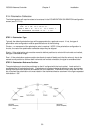
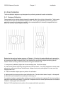
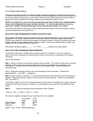
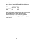
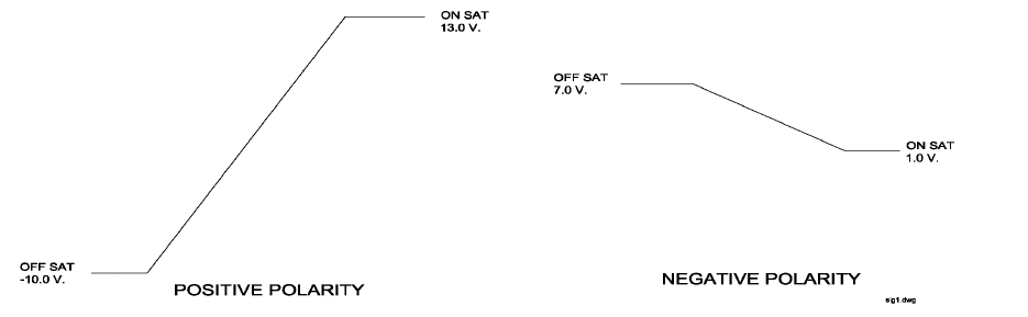
The following figure shows 2 examples of signal strength inputs that may be accommodated. Example A
shows a signal strength indication that increases from –10 VDC when no signal is present (“Off Satellite”)
to +13 VDC when the signal is strongest (“On Satellite”). With respect to the RC3000, this transition is
termed positive polarity. Example B shows a signal strength indication that decreases as the received
signal becomes stronger. This type of transition is termed negative polarity.
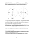
The goal of this procedure is to transform the linear portion of the signal strength input into a 0 to 5 VDC
signal for interpretation by the RC3000’s analog to digital conversion circuitry. This is accomplished by
adjusting gain and offset pots for each signal strength channel on the back of the RC3000 and by
specifying the polarity of the signal strength input via the signal strength configuration screen.