


RC3000 Antenna Controller Chapter 2 Installation
18
2.1 Equipment Mounting
This section describes the physical mounting requirements for the RC3000 and optional sensor units.
Wiring requirements are discussed in section 2.2.
2.1.1 RC3000 Antenna Controller
NOTE: The RC3000 unit should not be installed in the rack until the final step of the Initial
Configuration (section 2.3) because access to the interior of the unit may be necessary prior to
that procedure. The cables may be run through the chosen location in the rack and connected to
their respective components.
The RC3000 enclosure is a standard rack mount chassis that occupies two rack units (2U). The front
panel is mounted via four (4) 10-32 screws. Due to the length and weight of the RC3000, much strain
can be put on the faceplate, particularly in a mobile unit. To help alleviate stress on the front panel
mounting, additional mounting points accepting 10-32 and M4 screws are provided on each side, back
and bottom of the unit. The user may use any of these additional mounting points to provide support for
the RC3000 via strapping, shelving, etc. The additional mounting screws on the back of the unit may be
also used to provide strain relief for cabling.
CAUTION: support of the back of the RC3000 is a requirement. RCI’s warranty does not cover
repair to units with ripped faceplates.
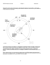
The RC3000’s LCD is optimized for viewing from a 6 o’clock position. The optimum position to mount the
unit would therefore be above the operator’s eye level.
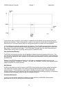
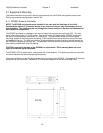
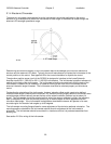
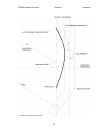
The following diagram shows the typical dimensions (in inches) of the RC3000. See appendix B for exact
dimensions of your controller. See section 5 for a detailed depiction of the side mounting holes.