


RC3000 Antenna Controller Chapter 4 Troubleshooting
132
After removing the wiring harness from J3, the first thing to check is that 12 VDC is present at the “+” pin
of each limit switch. Pins 2,9,10 and 11 should have +12 VDC present (see 2.2.4 – J3 wiring diagram.)
NOTE: pin 5 should also have +12 only if pins 11 and 13 are jumpered. If +12 VDC is not present, there
is a power supply failure within the RC3000. Contact your vehicle integrator, mount manufacturer or RCI
for further instructions on how to proceed.
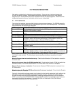
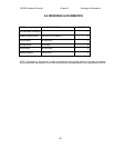
If +12 VDC is present, the limit switch sensing logic may be checked by jumpering between the
appropriate pins and noting if the limit switch condition is sensed correctly by the RC3000. The state of
the limit switches should be monitored via the Limits Maintenance (3.3.2.5) screen. The following table
shows which pins to jumper and state that should be seen via the Limits Maintenance screen.
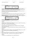
LIMIT J3 PINS JUMPERED OPEN
Azimuth STOW 9,7 1 0
Elevation DOWN 5,6* 0 1
Elevation STOW 11,13 0 1
Elevation UP 10,14 0 1
Polarization STOW 1,2 0 1
* - To test Elevation DOWN, pins 11 & 13 must be jumpered to simulate elevation not stowed
The azimuth CW/CCW and polarization CW/CCW limit conditions are mechanized by potentiometers
inside the RC3000 that should be set to correspond to the axis voltage at the limit conditions. If any of
these limits appear to be activating at the wrong time, check the setting of the potentiometers as
described in the azimuth and polarization calibration procedures (2.3.3 and 2.3.4.)
4.2 Motor Drive
Axis JAMMED error displayed. A jammed error indicates that the axis was commanded to move, but the
RC3000 did not sense any movement within several seconds. A jammed condition may indicate one of
several conditions:
The mount’s mechanical drive mechanism is physically jammed. Inspect the mount to determine if
some mechanical problem (slipped gears, etc) exists. Unusual conditions such as icing may also cause
the mount to jam.
The mount’s position is not being sensed correctly by the RC3000. After resetting the drive error, go
to MANUAL mode and attempt to jog the axis in question. If the axis does move, check to see if the axis’
displayed position is updating. If the RC3000 doesn’t sense movement, it will declare a jam even though
the axis is moving.
The RC3000’s motor drive is failing to output the required voltage to move the axis. Attempt to
move the axis in question via the MANUAL mode. There are several things to note:
1) When a jog key is pushed, can relays inside the RC3000 be heard activating? If no relays are heard,
a limit switch condition may be present that disallows movement in the axis in question. Review the
above limit switch discussion.
2) Can the axis move in slow speed but not in fast? If this is the case, the fast voltage setting or current
limit setting of the motor drive may need to be adjusted.
3) Is there voltage present at the appropriate J7 pins when the axis jog is attempted? If no voltage is
present, there’s the possibility that a fuse inside the RC3000 has blown (take care inside unit => must
disconnect power, etc.)
If a fuse is blown, replace with the appropriate fuse. Reconnect J7 and remove the drive wires at the
motors. Attempt to jog the axis. If the fuse blows again, the drive cables should be checked for a short.
If the fuse does not blow, the motor should be checked.
The axis’ motor is damaged. If possible, attempt to apply DC voltage to the motor from an external
source such as a series of batteries. If the motor will not move, the motor is probably damaged.