


RC3000 Antenna Controller Chapter 2 Installation
62
2.4.5 Operational Presets
This section has been included in the outline because it may simplify the user’s day-to-day operation.
The user cannot make use of preset truck locations or preset satellites if they are never entered into the
memory. This is a straightforward procedure, but one which can be overlooked once the system is
installed, since the RC3000 functions perfectly well without the presets. However, the presets streamline
the operation by allowing the user to tell the program very quickly where the truck is, and what satellite is
desired, without entering the data each time.
If a list of user preferred satellites or truck locations are available, they may be entered as described in
sections 3.3.1.1.2 and 3.3.1.1.3.
2.4.6 Miscellaneous Adjustments
LCD Contrast. An LCD contrast potentiometer (P2) is located on the RC3000 digital board. This
potentiometer will be set at the factory, but the user may want to adjust its setting for a particular
installation’s lighting conditions.
Setting Time. Set the time, specify local time zone and offset per instructions for Time Maintenance
(3.3.2.3.)
2.4.7 Mechanizing Automatic Locates
Performing all of the previous installation steps correctly should place the RC3000 into a state where
automatic locating of satellites may be accomplished. This section discusses the typical final actions
necessary to mechanize an automatic locate. The LOCATE mode is described in section 3.2.2.3.
The first issue typically related to LOCATE performance is the pointing accuracy of the compass. The
azimuth and elevation alignment calibration step (2.4.2) should be performed in order to fine tune the
mount’s position sensing.
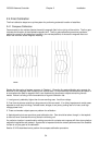
Even with a well calibrated compass, local magnetic effects will cause the estimated mount heading to
not be consistently perfect. Mechanizing the “autopeak” search movements described in sections
3.2.2.3.3 and 3.2.2.3.4 will provide a way to compensate for the inherent variability in heading estimate
performance.
In order to mechanize the autopeak function, the RC3000 must be interfaced with the antenna system’s
receiving equipment. The receiving equipment must provide a signal strength indication to the RC3000
as a “positive identification” of the selected satellite during the autopeak function. Section 3.3.1.2.6
describes enabling and configuring the autopeak function. Having selected a signal source, the
characteristics of the signal must be described to the RC3000 via the signal strength configuration screen
(3.3.1.2.5.)
Many variations of receiving equipment exist. The following provides one example setup.
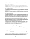
Example Usage. Suppose an installation has a modem that generates a signal lock output but no
relative signal strength output. An indication of relative signal strength may be obtained by inputting a
RF signal (2.2.8) into J11. The modem’s signal lock output may be input to either pin 1 or 2 of J2 (2.2.5.)
Program the RF LOCK item to indicate which signal lock input (1 or 2) is being used and what is the
polarity (high or low) of the signal lock input. Program the RF TIME item with a large enough delay to
ensure that a signal lock indication is generated by the modem before the autopeak scan operation steps
past the satellite of interest.
In the AUTOPEAK configuration screen (3.3.1.2.6), enable the autopeak function (ON:1) and set the
signal source to RF (SIG:1.)